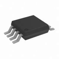
AD5310BRM-REEL Analog Devices Inc, AD5310BRM-REEL Datasheet - Page 11

AD5310BRM-REEL
Manufacturer Part Number
AD5310BRM-REEL
Description
IC DAC 10BIT R-R W/BUFF 8-MSOP
Manufacturer
Analog Devices Inc
Datasheet
1.AD5310BRMZ.pdf
(12 pages)
Specifications of AD5310BRM-REEL
Rohs Status
RoHS non-compliant
Settling Time
6µs
Number Of Bits
10
Data Interface
Serial
Number Of Converters
1
Voltage Supply Source
Single Supply
Power Dissipation (max)
1.25mW
Operating Temperature
-40°C ~ 105°C
Mounting Type
Surface Mount
Package / Case
8-MSOP, Micro8™, 8-uMAX, 8-uSOP,
Available stocks
Company
Part Number
Manufacturer
Quantity
Price
Company:
Part Number:
AD5310BRM-REEL7
Manufacturer:
AD
Quantity:
5 510
Company:
Part Number:
AD5310BRM-REEL7
Manufacturer:
PAN
Quantity:
5 510
REV. A
Bipolar Operation Using the AD5310
The AD5310 has been designed for single-supply operation
but a bipolar output range is also possible using the circuit in
Figure 30. The circuit below will give an output voltage
range of 5 V. Rail-to-rail operation at the amplifier output
is achievable using an AD820 or an OP295 as the output
amplifier.
The output voltage for any input code can be calculated as
follows:
where D represents the input code in decimal (0–1023).
With V
This is an output voltage range of 5 V with 000 Hex corre-
sponding to a –5 V output and 3FF Hex corresponding to a
+5 V output.
Using AD5310 with an Opto-Isolated Interface
In process-control applications in industrial environments it
is often necessary to use an opto-isolated interface in order to
protect and isolate the controlling circuitry from any hazard-
ous common-mode voltages which may occur in the area
where the DAC is functioning. Opto-isolators provide isola-
tion in excess of 3 kV. Because the AD5310 uses a three-wire
serial logic interface, it only requires three opto-isolators to
provide the required isolation (see Figure 31). The power
supply to the part also needs to be isolated. This is done by
using a transformer. On the DAC side of the transformer, a
+5 V regulator provides the +5 V supply required for the
AD5310.
+5V
10 F
Figure 30. Bipolar Operation with the AD5310
V
DD
O
= 5 V, R1 = R2 = 10 k :
0.1 F
V
DD
V
1024
THREE-WIRE
O
V
INTERFACE
D
DD
SERIAL
10 D
1024
AD5310
R1 R2
R1 = 10k
R1
– 5V
V
OUT
–V
DD
R2 = 10k
R2
R1
AD820/
OP295
+5V
–5V
5V
–11–
Power Supply Bypassing and Grounding
When accuracy is important in a circuit it is helpful to consider
carefully the power supply and ground return layout on the
board. The printed circuit board containing the AD5310 should
have separate analog and digital sections, each having their own
area of the board. If the AD5310 is in a system where other
devices require an AGND to DGND connection, the connec-
tion should be made at one point only. This ground point
should be as close as possible to the AD5310.
The power supply to the AD5310 should be bypassed with
10 F and 0.1 F capacitors. The capacitors should be physi-
cally as close as possible to the device with the 0.1 F capacitor
ideally right up against the device. The 10 F capacitors are the
tantalum bead type. It is important that the 0.1 F capacitor has
low Effective Series Resistance (ESR) and Effective Series In-
ductance (ESI), e.g., common ceramic types of capacitors. This
0.1 F capacitor provides a low impedance path to ground for
high frequencies caused by transient currents due to internal
logic switching.
The power supply line itself should have as large a trace as pos-
sible to provide a low impedance path and reduce glitch effects
on the supply line. Clocks and other fast switching digital signals
should be shielded from other parts of the board by digital
ground. Avoid crossover of digital and analog signals if possible.
When traces cross on opposite sides of the board ensure that
they run at right angles to each other to reduce feedthrough
effects through the board. The best board layout technique is
the microstrip technique where the component side of the board
is dedicated to the ground plane only and the signal traces are
placed on the solder side. However, this is not always possible
with a two-layer board.
SYNC
SCLK
Figure 31. AD5310 with an Opto-Isolated Interface
DATA
POWER
10k
10k
10k
V
V
V
REGULATOR
DD
DD
DD
+5V
SCLK
SYNC
DIN
AD5310
GND
V
DD
V
AD5310
OUT
10 F
0.1 F


