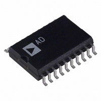
AD8804AR Analog Devices Inc, AD8804AR Datasheet - Page 13

AD8804AR
Manufacturer Part Number
AD8804AR
Description
IC DAC 8BIT 12CH W/SD 20-SOIC
Manufacturer
Analog Devices Inc
Series
TrimDAC®r
Datasheet
1.AD8804ARUZ-REEL.pdf
(16 pages)
Specifications of AD8804AR
Rohs Status
RoHS non-compliant
Settling Time
600ns
Number Of Bits
8
Data Interface
Serial
Number Of Converters
12
Voltage Supply Source
Single Supply
Power Dissipation (max)
60µW
Operating Temperature
-40°C ~ 85°C
Mounting Type
Surface Mount
Package / Case
20-SOIC (7.5mm Width)
Available stocks
Company
Part Number
Manufacturer
Quantity
Price
Part Number:
AD8804AR
Manufacturer:
ADI/亚德诺
Quantity:
20 000
Part Number:
AD8804ARU
Manufacturer:
ADI/亚德诺
Quantity:
20 000
Part Number:
AD8804ARUZ
Manufacturer:
ADI/亚德诺
Quantity:
20 000
Part Number:
AD8804ARZ
Manufacturer:
ADI/亚德诺
Quantity:
20 000
REV. 0
An Intelligent Temperature Control System—Interfacing the
8051 C with the AD8802/AD8804 and TMP14
Connecting the 80CL51 C, or any modern microcontroller,
with the TMP14 and AD8802/AD8804 yields a powerful tem-
perature control tool, as shown in Figure 27. For example, the
80CL51 C controls the TrimDACs allowing the user to auto-
matically set the temperature setpoints voltages of the TMP14
via computer or touch pad, while the TMP14 senses the tem-
perature and outputs four open-collector trip-points. Feeding
these trip-point outputs back to the 80CL51 C allow it to sense
whether or not a setpoint has been exceeded. Additional
80CL51 C port pins or TMP14 trip-point outputs may then
be used to change fan speed (i.e., high, medium, low, off), or
increase/decrease the power level to a heater. (Please refer to the
TMP14 data sheet for more applications information.)
The CS (Chip Select) on the AD8802/AD8804 makes applica-
tions that call for large temperature sensor arrays possible. In
addition, the 12 channels of the AD8802/AD8804 allow inde-
pendent setpoint control for all four trip-point outputs on up to
three TMP14 temperature sensors. For example, assume that
the 80CL51 C has eight free port pins available after all user
*
*
* Enter Contents of SDI2 Data Register
*
*
*
* Reset AD8802 to one-half scale (AD8804 does not have a Reset input)
*
*
* Get AD8802/04 ready for data input
*
*
TFRLP
*
WAIT
*
*
* Update AD8802 output
*
*
LDAA
STAA
LDAA
STAA
LDX
LDY
BCLR
BSET
BCLR
LDAA
STAA
LDAA
BPL
INX
CPX
BNE
BSET
PULA
PULY
PULX
RTS
Listing 3. AD8802/AD8804 to MC68HC11 Interface Program Source Code
$0000
SDI1
$0001
SDI2
#SDI1
#$1000
PORTC,Y $02
PORTC,Y $02
PORTD,Y $02
0,X
SPDR
SPSR
WAIT
#SDI2+1
TFRLP
PORTD,Y $20
Hi-byte data loaded from memory
SDI1 = data in location 0000H
Low-byte data loaded from memory
SDI2 = Data in location 0001H
Stack pointer at 1st byte to send via SDI
Stack pointer at on-chip registers
De-Assert /RS
Assert /CS
Get a byte to transfer for SPI
Write SDI data reg to start xfer
Loop to wait for SPIF
SPIF is the MSB of SPSR
Are we done yet ?
If not, xfer the second byte
Latch register & update AD8802
When done, restore registers X, Y & A
** Return to Main Program **
Assert /RS
Increment counter to next byte for xfer
–13–
interface lines, interrupts, and the serial port lines have been
assigned. The eight port pins may be used as chip selects, in
which case an array of eight AD8802/AD8804s controlling
twenty-four TMP14 sensors is possible.
The AD8802/AD8804 and TMP14 are also ideal choices for
low power applications. These devices have power shutdown
modes and operate on a single 5 Volt supply. When their shut-
down modes are activated current consumption is reduced to
less than 35 A. However, at high operating frequencies
(12 MHz) the 80CL51 consumes far more energy (18 mA typ)
than the AD8802/AD8804 and TMP14 combined. Therefore,
to achieve a low power design the 80CL51 should operate at its
lowest possible frequency or be placed in its power-down mode
at the end of each instruction sequence.
To use the power-down mode of the 80CL51 C set PCON.1
as the last instruction executed prior to going into the power-
down mode. If INT2 and INT9 are enabled, the 80CL51 C
can be awakened from power-down mode with external inter-
rupts. As shown in Figure 28, the TLC555 outputs a pulse
every few seconds providing the interrupt to restart the 80CL51
C which then samples the user input pins, the outputs of the
AD8802/AD8804


