PSK1212-9 POWER ONE, PSK1212-9 Datasheet - Page 11
PSK1212-9
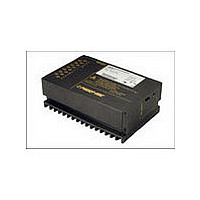
Manufacturer Part Number
PSK1212-9
Description
Manufacturer
POWER ONE
Type
Step Downr
Datasheet
1.PSK1212-9.pdf
(20 pages)
Specifications of PSK1212-9
Output Current
12A
Input Voltage
18 to 144V
Output Voltage
12V
Number Of Outputs
1
Output Power
144
Screening Level
Commercial
Operating Temperature Min Deg. C
-40C
Operating Temperature Max Deg. C
71C
Product Length (mm)
168.5mm
Product Depth (mm)
111mm
Product Height (mm)
80mm
Mounting Style
Screw
Pin Count
15
Lead Free Status / Rohs Status
Not Compliant


Fig. 7
Sense lines connection
Current Sharing
For parallel operation of several regulators, interconnect all T-
pins to ensure that the output currents are evenly distributed.
This feature improves transient load performance and
increases system reliability. All paralleled regulators should be
supplied by equal input voltage (V
exhibit equal length and cross section to provide equal voltage
drop.
Sense Lines
This feature enables compensation of the voltage drop across
the connector contacts and the load lines. If the sense lines are
connected at the load rather than directly at the connector, the
user must ensure that V
exceeded.
Applying generously dimensioned cross-section load leads
reduces the voltage drop. To minimize noise pick-up, the
sense lines should be wired in parallel or twisted.
To ensure correct operation, both sense lines must be
connected to their respective power output. The voltage
difference between any sense line and its respective power
output pin (as measured on the connector) should not exceed
the values given in table 4.
Table 6: Allowed voltage compensation using sense lines
Table 7: Maximum adjustable output voltage
BCD20029-G Rev AA, 28-Apr-09
Nominal output
V
V
Note: Sense lines should always be connected! It is
recommended to connect the sense lines directly at the female
connector.
3.3 V, 5.1 V
o nom
o max
12 – 48 V
voltage
Nominal Output Volt.
Maximum adjustable
output voltage with R-input
Vi+
i
R
T
Gi–
and their respective output
between both sense lines
Total voltage difference
Go –
®
06046a
Vo+
S+
S–
o max
0.5 V
1.0 V
(between Vo+ and Go–) is not
Conditions
V
i
). The output lines should
i nom
, I
o nom
Voltage difference
Go– and S–
between
Load
min
0.25 V
0.25 V
??
3.3 V
typ
Page 11 of 20
min
5.6
5.1 V
Fig. 8
Voltage adjustment via R-input
R Control (Output Voltage Adjust)
The output voltage V
voltage source (V
adjustment range is 0 – V
voltage V
Data) should be maintained.
a) V
b) V
c) V
Test Sockets
Test sockets (pin
V
regulator. The test sockets are protected by a series resistor.
LED Output Voltage Indicator
A green indicator LED illuminates, when the output voltage is
present.
typ
o
Note: With open R input, V
Caution: To prevent damage V
negative.
Caution: To prevent damage, R
k .
Vi+
Vi–
V
R
R
V
at the sense lines, are located at the front side of the
o
ext
1
o
o
2
o
= 0 – V
= 0 to V
= V
min
16
– ––– –––––––––––––––––––––––––––––
V
12/15 V
2.5 V • –––––
–––––––––––
4000
– ––– ––––––––––––––––––––––––––––––––––––
o nom
ref
2.5 V • (R
V
4000
io min
o nom
= 2.5 V
o max
2.5 V • (Vo – Vo nom)
typ
o nom
to V
Positive Switching Regulators
between input and output (see Electrical Input
– V
, using V
ext
V
• V
• V
PSS, PSK Series Data Sheet
, using R
o max
o nom
V
) or with an external resistor (R
o
2
min
26
V
= 2 mm) for measuring the output voltage
o
o
o
o
+ 4000
Control
o nom
24 V
4 k
logic
can either be adjusted with an external
• (V
, using R
typ
ext
o nom
o
• 2.5 V • R
1
between R and S–:
between R and S–:
o max
V
ext
V
06049a
) – V
o nom
V
o
2
min
42.5
– 2.5 V)
should not exceed 20 V, nor be
2
o
should never be less than 47
. The minimum differential
36 V
between R and S+:
16
18
.
20
o nom
R
–––––––––––
V
V
typ
1
S+
R
S–
2
o nom
o nom
+ 4000
• 4000
R
R
• R
• –––––
min
52.8
www.power-one.com
ext2
ext1
48 V
2.5 V
V
1
ext
typ
1
+
-
or R
2
Unit
V
). The
V
ext
Related parts for PSK1212-9
Image
Part Number
Description
Manufacturer
Datasheet
Request
R

Part Number:
Description:
SWITCHING POWER SUPPLIES, SINGLE OUTPUT, 80 WATTS
Manufacturer:
POWER ONE
Datasheet:
Part Number:
Description:
HAS SERIES - 30 WATT
Manufacturer:
POWER ONE
Datasheet:
Part Number:
Description:
SINGLE OUTPUT
Manufacturer:
POWER ONE
Datasheet:

Part Number:
Description:
BRS DC/DC converters(1.5 WATT)
Manufacturer:
Power-One
Datasheet:
Part Number:
Description:
3...15 Watt DC-DC Converter
Manufacturer:
Power-One
Datasheet:
Part Number:
Description:
HBS SERIES - 100 WATT
Manufacturer:
Power-One
Datasheet:
Part Number:
Description:
3...15 Watt DC-DC Converter
Manufacturer:
Power-One
Datasheet:
Part Number:
Description:
BUS DC/DC converters(3 WATT)
Manufacturer:
Power-One
Datasheet:
Part Number:
Description:
HES SERIES 150 WATT
Manufacturer:
Power-One
Datasheet:
Part Number:
Description:
1.25 WATT
Manufacturer:
Power-One
Datasheet: