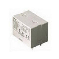
G7L2APCBDC24 Omron, G7L2APCBDC24 Datasheet

G7L2APCBDC24
Specifications of G7L2APCBDC24
Related parts for G7L2APCBDC24
G7L2APCBDC24 Summary of contents
Page 1
... DPST-NO PCB mounting SPST-NO DPST-NO Note bracket or socket must be used for mounting (part number R99-07G5D). Refer to “Accessories” section for options and part numbers. 2. For VDE approved versions, please consult OMRON. Model Quick-connect terminal Screw terminal G7L-1A-T-CB G7L-1A-B-CB ...
Page 2
... Quick-connect Terminals Description E-brackets G7L-1A-T Track mounting adaptor Front connecting socket Note: A socket terminal cover is supplied with the P7LF-06 socket and does not attach directly to the G7L relays. It cannot be purchased separately. Screw Terminals Description E-brackets G7L-1A-B Track mounting adaptor Terminal Cover Note: The P7LF-C terminal cover attaches directly to the G7L-B style relays ...
Page 3
Coil Data AC Rated voltage Rated current (V) (mA) 6 283 18.90 12 142 303 50 34 1,310 100/120 17.00/20.40 5,260 200/240 8.50/10.20 21,000 DC Rated voltage Rated current (V) (mA) 6 317 18.90 12 158 ...
Page 4
... Characteristic Data Maximum switching capacity Switching voltage (V) Dimensions Unit: mm (inch) ■ Relays G7L-1A-T (E Bracket Attached)* G7L-2A-T (E Bracket Attached bracket must be ordered separately. 308 General Purpose Relay Electrical service life Switching current (A) Terminal arrangement/ Internal connections (Top view) Terminal arrangement/ Internal connections ...
Page 5
G7L-1A-TJ (E Bracket Attached)* G7L-2A-TJ (E Bracket Attached)* G7L-1A-TUB G7L-2A-TUB *E bracket must be ordered separately. Terminal arrangement/ Internal connections (Top view) Terminal arrangement/ Internal connections (Top view) Terminal arrangement/ Internal connections (Top view) Terminal arrangement/ Internal connections (Top view) ...
Page 6
Unit: mm (inch) G7L-1A-TUBJ G7L-2A-TUBJ G7L-1A-B (E bracket Attached)* G7L-2A-B (E bracket Attached bracket must be ordered separately. 310 General Purpose Relay Terminal arrangement/ Internal connections (Top view) Terminal arrangement/ Internal connections (Top view) Terminal arrangement/ Internal connections ...
Page 7
G7L-1A-BJ (E bracket Attached)* G7L-2A-BJ (E bracket Attached)* G7L-1A-BUB G7L-2A-BUB * E bracket must be ordered separately. Terminal arrangement/ Internal connections (Top view) Terminal arrangement/ Internal connections (Top view) Terminal arrangement/ Internal connections (Top view) Terminal arrangement/ Internal connections (Top ...
Page 8
Unit: mm (inch) G7L-1A-BUBJ G7L-2A-BUBJ G7L-1A-P G7L-2A-P 312 General Purpose Relay Terminal arrangement/ Internal connections (Top view) Terminal arrangement/ Internal connections (Top view) Terminal arrangement/ Internal connections (Top view) Terminal arrangement/ Internal connections (Top view) G7L Mounting holes (Bottom view) ...
Page 9
Accessories E bracket R99-07G5D Adaptor P7LF-D Front connecting socket P7LF-06 Note protect against electric shock, a socket terminal cover is supplied with the P7LF-06 socket. 2. The P7LF-06 is panel or track mountable. Mounting holes (Bottom view) ...
Page 10
... Unit: mm (inch) Cover P7LF-C Note: P7LF-C cover attaches directly to G7L-B style relays. To protect against electric shock, use the P7LF-C on G7L-B terminals. Mounting track PFP-100N, PFP-50N (Conforming to EN 50022) 7.3±0.15 4.5 35±0 ( 1000 (500)* * The figure in parenthesis is for PFP-50N. Note recommended that a panel thickness of 1.60 to 2.00 mm (0.06 to 0.08 in) be used. ...
Page 11
... G7L-2A-BUBJ-CB G7L-2A-P-CB VDE recognized type (Licence no. 1530 UG) Note: 1. Please consult OMRON for details of VDE approvals. 2. The G7L relay conforms to the following standards: 3. The rated values approved by each of the safety standards (e.g., UL and CSA) may be different from the performance characteristics individually defined in this catalog. ...
Page 12
... General Purpose Relay ■ Operating Coil • rule, either a battery power supply with a maximum 5% ripple is used for the operating voltage for DC relays. Before using a rectified AC supply, confirm that the ripple is not greater than 5%. Ripple greater than this can lead to variations in the oper- ating and reset voltages ...
Page 13
... Seller within 30 days of receipt of shipment. III. PRECAUTIONS 1. Suitability THE BUYER’S SOLE RESPOINSIBILITY TO ENSURE THAT ANY OMRON PRODUCT IS FIT AND SUFFICIENT FOR USE IN A MOTORIZED VEHICLE APPLICATION. BUYER SHALL BE SOLELY RESPONSIBLE FOR DETERMINING APPROPRIATENESS OF THE PARTICULAR PRODUCT WITH RESPECT TO THE BUYER’ ...
Page 14
... THE OMRON PRODUCT IS PROPERLY RATED AND INSTALLED FOR THE INTENDED USE WITHIN THE OVERALL EQUIPMENT OR SYSTEM. Complete “Terms and Conditions of Sale” for product purchase and use are on Omron’s website at http://www.components.omron.com – under the “About Us” tab, in the Legal Matters section. ...


