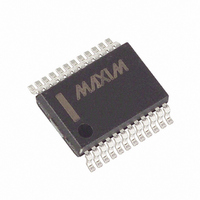
MAX521ACAG+ Maxim Integrated Products, MAX521ACAG+ Datasheet

MAX521ACAG+
Specifications of MAX521ACAG+
Related parts for MAX521ACAG+
MAX521ACAG+ Summary of contents
Page 1
... AGND 5 DGND 6 SCL 7 SDA 8 DIP/SO Pin Configurations continued at end of data sheet. ________________________________________________________________ Maxim Integrated Products For free samples & the latest literature: http://www.maxim-ic.com, or phone 1-800-998-8800 with Rail-to-Rail Outputs ____________________________Features Single +5V Supply Simple 2-Wire Serial Interface Compatible Outputs Swing Rail to Rail: ...
Page 2
Quad/Octal, 2-Wire Serial 8-Bit DACs with Rail-to-Rail Outputs ABSOLUTE MAXIMUM RATINGS V to DGND ...........................................................-0. AGND............................................................-0.3V to +6V DD OUT_ ..........................................................-0. REF_ ...........................................................-0. AD0, AD1, AD2...........................................-0. SCL, SDA to ...
Page 3
Quad/Octal, 2-Wire Serial 8-Bit DACs ELECTRICAL CHARACTERISTICS (continued ±10 4V (MAX520 REF_ L unless otherwise noted. Typical values are at T PARAMETER REFERENCE INPUTS Input Voltage Range Input Resistance Input Current ...
Page 4
Quad/Octal, 2-Wire Serial 8-Bit DACs with Rail-to-Rail Outputs ELECTRICAL CHARACTERISTICS (continued ±10 4V (MAX520 REF_ L unless otherwise noted. Typical values are at T PARAMETER DYNAMIC PERFORMANCE Voltage Output Slew Rate ...
Page 5
Quad/Octal, 2-Wire Serial 8-Bit DACs TIMING CHARACTERISTICS ( ±10 unless otherwise noted. Typical values are MIN MAX PARAMETER Serial Clock Frequency Bus Free Time Between a STOP and ...
Page 6
Quad/Octal, 2-Wire Serial 8-Bit DACs with Rail-to-Rail Outputs ______________________________Typical Operating Characteristics (continued 5V, DAC outputs unloaded +25°C, unless otherwise noted MAX520 POSITIVE SETTLING TIME 1 s/div OUT2 = NO LOAD, REF2 = 4V, DAC ...
Page 7
Quad/Octal, 2-Wire Serial 8-Bit DACs __________________________________________Typical Operating Characteristics (V = 5V, DAC outputs unloaded MAX521 SUPPLY CURRENT vs. TEMPERATURE 5.5V DD ALL REF INPUTS = 0.6V 10 ALL DIGITAL INPUTS ALL ...
Page 8
Quad/Octal, 2-Wire Serial 8-Bit DACs with Rail-to-Rail Outputs ______________________________Typical Operating Characteristics (continued 5V, DAC outputs unloaded +25°C, unless otherwise noted CLOCK FEEDTHROUGH A = SCL, 400kHz, 5V/div B = OUT1, 5mV/div REF1 = 5V, ...
Page 9
Quad/Octal, 2-Wire Serial 8-Bit DACs ______________________________________________________________Pin Description PIN MAX520 DIP/SO SSOP — 14 — — — — — — — — ...
Page 10
Quad/Octal, 2-Wire Serial 8-Bit DACs with Rail-to-Rail Outputs _______________Detailed Description The MAX520/MAX521 use a simple 2-wire serial interface requiring only two I/O lines (2-wire bus standard microprocessor (µP) port. Figure 1 shows the timing dia- gram for signals ...
Page 11
Quad/Octal, 2-Wire Serial 8-Bit DACs START and STOP Conditions When the bus is not in use, both SCL and SDA must be high. A bus master signals the beginning of a transmis- sion with a START condition by transitioning SDA ...
Page 12
Quad/Octal, 2-Wire Serial 8-Bit DACs with Rail-to-Rail Outputs 0 OR AD2 AD1 AD0 0 0 SDA ADDRESS BYTE ACK START CONDITION SDA OUTPUT BYTE ACK (FULL SCALE) ( ...
Page 13
Quad/Octal, 2-Wire Serial 8-Bit DACs 0 OR AD2 ( AD1 AD0 0 0 SDA ADDRESS BYTE ACK START CONDITION 0 OR AD2 ( AD1 AD0 SDA ADDRESS BYTE ACK ...
Page 14
Quad/Octal, 2-Wire Serial 8-Bit DACs with Rail-to-Rail Outputs SDA ADDRESS BYTE ACK (DEVICE 0) START CONDITION SDA ACK COMMAND BYTE (ADDRESSING ...
Page 15
Quad/Octal, 2-Wire Serial 8-Bit DACs REF_ AGND SHOWN FOR ALL 1s ON DAC Figure 14. DAC Simplified Circuit Diagram ( code dependent, it must be driven by a ...
Page 16
Quad/Octal, 2-Wire Serial 8-Bit DACs with Rail-to-Rail Outputs DAC (1%) Figure 15a. Typical Trimming Circuit __________Applications Information Shutdown Mode In shutdown mode, the MAX520/MAX521 reference inputs are disconnected from the R-2R ladder inputs, which saves power ...
Page 17
Quad/Octal, 2-Wire Serial 8-Bit DACs ___________________________________________________Pin Configurations (continued) TOP VIEW OUT1 1 20 OUT0 2 19 REF1 MAX520 REF0 5 16 AGND DGND 13 8 SCL 12 9 SDA 10 ...
Page 18
Quad/Octal, 2-Wire Serial 8-Bit DACs with Rail-to-Rail Outputs __Ordering Information (continued) † PART TEMP. RANGE PIN-PACKAGE MAX520ACAP 0°C to +70°C 20 SSOP MAX520BCAP 0°C to +70°C 20 SSOP MAX520AC/D 0°C to +70°C Dice* MAX520BC/D 0°C to +70°C Dice* MAX520AEPE -40°C ...
Page 19
Quad/Octal, 2-Wire Serial 8-Bit DACs ________________________________________________________Package Information ______________________________________________________________________________________ with Rail-to-Rail Outputs 0° - 15° Plastic DIP PLASTIC DUAL-IN-LINE PACKAGE (0.300 ...
Page 20
... Maxim cannot assume responsibility for use of any circuitry other than circuitry entirely embodied in a Maxim product. No circuit patent licenses are implied. Maxim reserves the right to change the circuitry and specifications without notice at any time. 20 __________________Maxim Integrated Products, 120 San Gabriel Drive, Sunnyvale, CA 94086 (408) 737-7600 © 1996 Maxim Integrated Products ...


