OY47GK-E Ohmite, OY47GK-E Datasheet
OY47GK-E
Manufacturer Part Number
OY47GK-E
Description
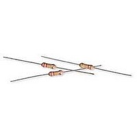
Ceramic Composition Resistors 2watt 4.7ohm 10% HIGH ENERGY
Manufacturer
Ohmite
Series
OYr
Datasheet
1.OY562K.pdf
(1 pages)
Specifications of OY47GK-E
Resistance
4.7 Ohms
Tolerance
10 %
Power Rating
2 Watts
Voltage Rating
400 Volts
Temperature Coefficient
- 1300 PPM / C to +/- 300 PPM / C
Termination Style
Axial
Dimensions
7 mm Dia. x 19 mm L
Operating Temperature Range
- 40 C to + 220 C
Product
Resistors Ceramic Composition
Lead Free Status / Rohs Status
Lead free / RoHS Compliant
OX/OY Series
Ceramic Composition
10% Tolerance
The OX/OY Series of fixed ceramic resistors are ideal for circuit-
ry associated with surges, high peak power or high energy. They
offer enhanced performance in high voltage power supplies, R-C
snubber circuits, and inrush limiters. The OX/OY resistors can
often replace carbon composition resistors which can be difficult
to source.
r e S i S T A n C e T O p u L S e
56
10
12
15
18
22
* at 70°C. **For a single impulse.
3.3 ––33GKE
3.9 ––39GKE
4.7 ––47GKE
5.6 ––56GKE
6.8 ––68GKE
8.2 ––82GKE
0.80%
0.60%
0.40%
0.20%
0.00%
0.80%
0.60%
0.40%
0.20%
0.00%
Series
Max. Pulse
Voltage
10 kohm
OX
OY
––100KE
––120KE
––150KE
––180KE
––220KE
Ohmite Mfg. Co.
part no.
Prefix
Suffix
0
0
1 sec. on / 1 sec. off
OY Series
OX Series
taped & reeled units
*approx. 27mm for
38.0mm ±3*
1.50" ±.118
max.*
Watts
Wattage
1
2
100
100
1000 pF
min.
100
120
150
180
1600 Golf Rd., Rolling Meadows, IL 60008 • 1-866-9-OHMITE • Int’l 1-847-258-0300 • Fax 1-847-574-7522 • www.ohmite.com • info@ohmite.com
resistance
3.3
3.3
27
33
39
47
56
68
82
Cycles
Cycles
1,000
1,000
R.U.T.
––270KE
––330KE
––390KE
––470KE
––560KE
––680KE
––820KE
––101KE
––121KE
––151KE
––181KE
part no.
Prefix
Suffix
100K
max.
1M
14KV and 20KV
values used in cir-
cuit as shown; full
voltage not applied
directly to resistor.
C
L
Wattage
10,000
10,000
±.039 (±1.0)
0.748 / 19.0
0.65 / 16.5
Length L
test conditions
test conditions
see circuit for
see circuit for
S t a n d a r d p a r t n u m b e r S f o r o x / o y S e r i e S
DC 20KV
DC 14KV
Dimensions (in. / mm)
1000 ––102KE
1200 ––122KE
1500 ––152KE
D
20,000
20,000
220 ––221KE
270 ––271KE
330 ––331KE
390 ––391KE
470 ––471KE
560 ––561KE
680 ––681KE
820 ––821KE
0.748 / 19.0
0.886 / 22.5
10 Kohms
1 Kohm
100 ohms
10 Kohms
1 Kohm
100 ohms
Length C
part no.
Prefix
Suffix
0.031" nom.
(0.8mm)
max.
2.5mm
Wattage
T A p e D i M e n S i O n S
max.
±.039 (±1.0)
Diameter D
0.217 / 5.5
0.276 / 7.0
L
1
10000 ––103KE
12000 ––123KE
L
– L
1800 ––182KE
2200 ––222KE
2700 ––272KE
3300 ––332KE
3900 ––392KE
4700 ––472KE
5600 ––562KE
6800 ––682KE
8200 ––822KE
1
63mm ±1
F e A T u r e S
• Replaces 1 and 2 watt carbon
• Meets high energy density
• High peak power
• 10% Tolerance
Test
Max Working Voltage
Dielectric Strength
Max Overload Voltage
Max Pulse Voltage
Pulse Tolerance, 100 pulses
Test
Life Test
Short Time Overload
Resistance to Pulse
Thermal Shock
Moisture Resistance
1
See figures, left
2
composition resistors
demands
= 1mm max.
part no.
Prefix
Suffix
max.**
Joules
50
80
L
6.2mm ±.5
2
Wattage
p e r f o r m a n c e c h a r a c t e r i S t i c S
1
1
Working
20,000 cycles
volts
Max
300
400
10.16mm ±.80
0.80mm
100000 ––104KE
max.
15000 ––153KE
18000 ––183KE
22000 ––223KE
27000 ––273KE
33000 ––333KE
39000 ––393KE
47000 ––473KE
56000 ––563KE
68000 ––683KE
82000 ––823KE
1240V @ 52µF, 40J/ 35 sec.
Qty.
per
reel
1000
500
1000 hrs @ 40°C, 90 - 95% RH
part no.
Prefix
Suffix
see circuit for test conditions
2x rated V, 5 sec ON @ 70°C
MIL-STD-202, Method 108
MIL-STD-202, Method 107
O X 8 2 G K E
Size
OX = 1W
OY = 2W
r e e L D i M e n S i O n S
o r d e r i n G i n f o r m a t i o n
300V
500V
600V
14KV
OX
S p e C i F i C A T i O n S
Material
Terminals: Pb-free solder-coated
Coating: Silicone ceramic
Derating: Linear from 100% @
Operating Temp. Range: -40°C
Electrical
Tolerance: ±10% standard
Power Rating: Based on 70°C
Temperature Coefficient:
Condition
Wattage
axial
+70°C to 0% @ +200°C
to +220°C
free air rating.
-1300 ±300ppm/°C.
Ohm Value
Example:
33G = 3.3 Ohms
330 = 33 Ohms
331 = 330 Ohms
13"
RoHS Compliant
120000 ––124KE
150000 ––154KE
180000 ––184KE
220000 ––224KE
270000 ––274KE
330000 ––334KE
390000 ––394KE
470000 ––474KE
560000 ––564KE
680000 ––684KE
820000 ––824KE
ø 1.13"
1 MEG
1640V @ 52µF, 70J/35 sec.
Tolerance
K = 10% Standard
part no.
Prefix
Suffix
––105KE
±(2% ± 0.05 ohm)
±(2% + 0.05ohm)
Maximum ∆r
20KV
400V
700V
800V
OY
Tape & reel
optional
-TR
±5%
±5%
±5%
3"
Wattage
2.88"
Related parts for OY47GK-E
Image
Part Number
Description
Manufacturer
Datasheet
Request
R

Part Number:
Description:
RES CERAMIC COMP 4.7 OHM 2W
Manufacturer:
Ohmite
Datasheet:

Part Number:
Description:
RESISTOR POWER 1.0 OHM 50W
Manufacturer:
Ohmite
Datasheet:

Part Number:
Description:
POINTER BAR KNOB, 6.35MM
Manufacturer:
Ohmite
Datasheet:

Part Number:
Description:
HAND WHEEL POINTER KNOB, 9.525MM
Manufacturer:
Ohmite
Datasheet:

Part Number:
Description:
FINGER GRIP KNOB, 3.175MM
Manufacturer:
Ohmite
Datasheet:


Part Number:
Description:
MOUNTING CLIP, 90 SERIES RESISTOR
Manufacturer:
Ohmite
Datasheet:

Part Number:
Description:
ADJUSTABLE LUG FOR DIVIDOHM
Manufacturer:
Ohmite
Datasheet:
Part Number:
Description:
ADJUSTABLE LUG FOR DIVIDOHM
Manufacturer:
Ohmite
Datasheet:

Part Number:
Description:
RESISTOR POWER 1.0 OHM 50W
Manufacturer:
Ohmite
Datasheet:
Part Number:
Description:
HAND WHEEL POINTER KNOB, 9.525MM
Manufacturer:
Ohmite
Datasheet:

Part Number:
Description:
RHEOSTAT REPAIR KIT
Manufacturer:
Ohmite
Datasheet: