HL55-09Z 250 5% Vishay, HL55-09Z 250 5% Datasheet - Page 2
HL55-09Z 250 5%
Manufacturer Part Number
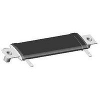
HL55-09Z 250 5%
Description
Wirewound Resistors 55watts 250ohms 5%
Manufacturer
Vishay
Datasheet
1.HLM01510Z16K50JJ.pdf
(3 pages)
Specifications of HL55-09Z 250 5%
Resistance
250 Ohms
Tolerance
5 %
Power Rating
55 Watts
Temperature Coefficient
+/- 30 PPM / C
Dimensions
30.16 mm W x 88.9 mm L
Product
Power Resistors Wire Wound Silicon Coated
Lead Free Status / Rohs Status
Lead free / RoHS Compliant


HL, NHL FLAT
Vishay Dale
DIMENSIONS in inches [millimeters]
TYPE HL FLAT STYLE
POWER RATING
Vishay HL flat resistor wattage ratings are based on
mounting horizontally to 10" x 10" x 0.04" [254.0 mm x
254.0 mm x 1.02 mm] steel plate in 25 °C ambient with no
air flow.
EXCLUSIVE BRACKET DESIGN
Mounting strap fits snugly through resistor core and is
bound against unit by two eccentric spacers. The bracket
eliminates expensive cements and improves heat transfer
and power handling capabilities.
MATERIAL SPECIFICATIONS
Element: Copper-nickel alloy of nickel-chrome alloy,
depending on resistance value
Core: Ceramic, steatite
Coating: Special high temperature silicone
Standard Terminals: Model “E” terminals are tinned steel
Terminal Bands: Steel
Part Marking: DALE, model, wattage, value, tolerance, date
code
www.vishay.com
2
[11.11 ± 0.794]
0.438 ± 0.030
MODEL
HL024
NHL024 [31.75]
HL035
NHL035 [50.80]
HL055
NHL055 [88.90] [120.65] [107.95]
HL070
NHL070 [120.65] [152.40] [139.70]
HL095
NHL095 [152.40] [184.15] [171.45]
PERFORMANCE
TEST
Thermal Shock
Short Time Overload
Dielectric Withstanding Voltage
Low Temperature Storage
High Temperature Exposure
Moisture Resistance
Shock, Specified Pulse
Vibration, High Frequency
Load Life
1.188 [30.16]
max.
± 0.063
[1.59]
1.250
2.000
3.500
4.750
6.000
A
± 0.063
[63.50]
[82.55]
[1.59]
2.500
3.250
4.750
6.000
7.250
DIMENSIONS in inches [millimeters]
B
± 0.031
[50.80]
[69.85]
[0.79]
2.000
2.750
4.250
5.500
6.750
C
A
C
B
TERMINALS
DISTANCE
BETWEEN
[107.14]
[138.89]
[18.24]
[37.29]
[75.39]
0.718
1.468
2.968
4.218
5.468
Rated power applied until thermally stable,then a minimum of 15 min at - 55 °C
10 x rated power for 5 s
1000 V
- 55 °C for 24 h
250 h at + 350 °C
MIL-STD-202 Method 106, 7b not applicable
MIL-STD-202 Method 213, 100 's for 6 ms, 10 shocks
Frequency varied 10 Hz to 2000 Hz, 20 g peak, 2 directions 6 h each
1000 h at rated power, + 25 °C, 1.5 h “ON”, 0.5 h “OFF”
(ref.)
For technical questions, contact:
RMS
0.196 [4.98] Dia. typ.
STANDARD OPTIONAL
Wirewound Resistors, Industrial
, 1 min
0.313 [7.94] Dia.
09Z
09Z
09Z
09Z
09Z
0.625 [15.88]
DESIGNATION
TERMINAL
0.594 [15.08]
0.563 ± 0.030
[14.29 ± 0.794]
Power, Flat (HL)
16N
16N
16N
16N
16N
CONDITIONS OF TEST
ww2bresistors@vishay.com
TERMINAL DIMENSIONS
TERMINAL FINISH
“E” Finish - 100 % Sn coated steel. “Z” Finish - 60/40 Sn/Pb
coated steel. “N” Finish - Nickel coated steel. Finish for
terminal style 16 is limited to nickel plated steel (N).
NHL NON-INDUCTIVE
Models of equivalent physical and electrical specifications
are available with non-inductive (Aryton-Perry) winding.
They are identified by adding the letter N to the front of the
HL type designation (NHL024, for example). For NHL
models maximum resistance values are lower, see
STANDARD ELECTRICAL SPECIFICATIONS table.
Derating is required for ambient temperatures above 25 °C
per the following graph.
DERATING
DIMENSION
A
B
C
D
Style 09
120
100
80
60
40
20
- 65 - 50
0
A
C
0
25
B
50
DIMENSIONS in inches [millimeters]
STYLE 09
[12.70]
0.188
[4.76]
0.500
0.104
[2.64]
0.020
[0.51]
D
150
AMBIENT TEMPERATURE IN
Style 16
Document Number: 30209
A
C
± (2.0 % + 0.05 Ω) Δ
± (2.0 % + 0.05 Ω) Δ
± (0.1 % + 0.05 Ω) Δ
± (2.0 % + 0.05 Ω) Δ
± (2.0 % + 0.05 Ω) Δ
± (2.0 % + 0.05 Ω) Δ
± (0.2 % + 0.05 Ω) Δ
± (0.2 % + 0.05 Ω) Δ
± (3.0 % + 0.05 Ω) Δ
250
TEST LIMITS
Revision: 11-Jan-11
STYLE 16
[14.29]
B
0.188
0.563
0.050
0.020
[4.76]
[1.27]
[0.51]
°
350
C
D
Related parts for HL55-09Z 250 5%
Image
Part Number
Description
Manufacturer
Datasheet
Request
R

Part Number:
Description:
Wirewound Resistors 55watts 150ohms 5%
Manufacturer:
Vishay
Datasheet:
Part Number:
Description:
Wirewound Resistors 55watts 3ohms 5%
Manufacturer:
Vishay
Datasheet:
Part Number:
Description:
Wirewound Resistors 55watts 4ohms 5%
Manufacturer:
Vishay
Datasheet:

Part Number:
Description:
357-036-542-201 CARDEDGE 36POS DL .156 BLK LOPRO
Manufacturer:
Vishay
Datasheet:
Part Number:
Description:
357-036-542-201 CARDEDGE 36POS DL .156 BLK LOPRO
Manufacturer:
Vishay
Datasheet:
Part Number:
Description:
357-036-542-201 CARDEDGE 36POS DL .156 BLK LOPRO
Manufacturer:
Vishay
Datasheet:
Part Number:
Description:
357-036-542-201 CARDEDGE 36POS DL .156 BLK LOPRO
Manufacturer:
Vishay
Datasheet:
Part Number:
Description:
357-036-542-201 CARDEDGE 36POS DL .156 BLK LOPRO
Manufacturer:
Vishay
Datasheet:
Part Number:
Description:
357-036-542-201 CARDEDGE 36POS DL .156 BLK LOPRO
Manufacturer:
Vishay
Datasheet:
Part Number:
Description:
357-036-542-201 CARDEDGE 36POS DL .156 BLK LOPRO
Manufacturer:
Vishay
Datasheet:
Part Number:
Description:
357-036-542-201 CARDEDGE 36POS DL .156 BLK LOPRO
Manufacturer:
Vishay
Datasheet:
Part Number:
Description:
357-036-542-201 CARDEDGE 36POS DL .156 BLK LOPRO
Manufacturer:
Vishay
Datasheet:
Part Number:
Description:
357-036-542-201 CARDEDGE 36POS DL .156 BLK LOPRO
Manufacturer:
Vishay
Datasheet:
Part Number:
Description:
357-036-542-201 CARDEDGE 36POS DL .156 BLK LOPRO
Manufacturer:
Vishay
Datasheet:
Part Number:
Description:
357-036-542-201 CARDEDGE 36POS DL .156 BLK LOPRO
Manufacturer:
Vishay
Datasheet: