PVZ3A501A01R00 Murata, PVZ3A501A01R00 Datasheet - Page 81
PVZ3A501A01R00
Manufacturer Part Number
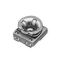
PVZ3A501A01R00
Description
Trimmer Resistors - SMD 500 OHM SMD 3MM
Manufacturer
Murata
Series
PVZ3Ar
Specifications of PVZ3A501A01R00
Resistance
500 Ohms
Tolerance
30 %
Power Rating
0.1 Watt (1/10 Watt)
Operating Temperature Range
- 25 C to + 85 C
Element Type
Carbon
Number Of Turns
1
Product
Single-Turn Trimmer Potentiometers
Taper
Linear
Termination Style
SMD/SMT
Lead Free Status / Rohs Status
Lead free / RoHS Compliant


9
!Note
• This PDF catalog is downloaded from the website of Murata Manufacturing co., ltd. Therefore, it’s specifications are subject to change or our products in it may be discontinued without advance notice. Please check with our
• This PDF catalog has only typical specifications because there is no space for detailed specifications. Therefore, please approve our product specifications or transact the approval sheet for product specifications before ordering.
sales representatives or product engineers before ordering.
!Note
80
No.
10
The tests and measurements should be conducted under the condition of 15 to 35°C of temperature 25 to 75% of relative humidity and 86 to 106 k Pa of
atmospheric pressure unless otherwise specified. In case when entertained a doubt in judgment obtained from results measured in accordance with the
above mentioned conditions, the tests and measurements should be conducted under the condition of 25±2°C of temperature and, 50±2% of relative
humidity and 86 to 106 k Pa of atmospheric pressure. When the potentiometer is tested after soldering on PCB., it should be tested after being kept in a
room (15 to 35°C, 25 to 75%RH) over 24 hours except "Resistance to soldering heat".
Rortary Position Sensors SMD/Lead Dust-proof Type (SV01) Specifications and Test Methods
1
2
3
4
5
6
7
8
9
Linearity
Temperature
Coefficient of
Resistance
Temperature
Cycle
(Thermal Shock)
Humidity
Vibration
Shock
Humidity Load
Life
High Temp.
Exposure
Low Temp.
Exposure
Rotational Life
• Please read rating and !CAUTION (for storage, operating, rating, soldering, mounting and handling) in this catalog to prevent smoking and/or burning, etc.
• This catalog has only typical specifications because there is no space for detailed specifications. Therefore, please approve our product specifications or transact the approval sheet for product specifications before ordering.
Item
Independent linearity should vary no more than ±2% within ±160° to 50% voltage ratio.
Taper : linear, 100%/333.3° Measured with the circuit as below (Figure 1).
The rotary position sensor should be subjected to each of the following temperatures (see Table 1) for 30-45 minutes.
Temperature coefficient of resistance should be applied to the following formula.
TCR=
The rotary position sensor should be subjected to Table 2 temperature for 5 cycles.
Then, the rotary position sensor should be kept in the dry box for 24 +8/-0 hrs.
The rotary position sensor should be stored in a chamber at temperature of +60±2°C and relative Humidity of 90-95% for 250±8
hrs. After removing from the chamber, the rotary position sensor should be kept in the dry box for 24 +8/-0 hours.
The rotary position sensor should be tested under the condition of the amplitude of 1.5mm, the frequency range from 10 to 55Hz
(should be traversed in approximately one minute) and 2 hours in each of 3 mutually perpendicular directions (total 6 hours).
Then, the rotary position sensor should be kept in the dry box for 1-2 hrs.
The rotary position sensor should be tested under the condition of the peak acceleration 20G max. in half-sine wave and 5 shocks
in each of 3 mutually perpendicular directions (total 15 shocks). Then, the rotary position sensor should be kept in the dry box for
1-2 hrs.
Full rated continuous working voltage not exceeding 5Vdc should be applied intermittently between terminal #1 and terminal #3 of
the rotary position sensor, 1.5 hours on and 0.5 hours off, for 96±4 hours in total in a chamber at a temperature of +40±2°C and
relative humidity of 90-95%. After removing from the chamber, the rotary position sensor should be kept in the dry box for 24 +8/-
0 hours.
The rotary position sensor should be stored in a chamber at the temperature of +85±3°C without loading for 250±8 hours. After
removing from the chamber, the rotary position sensor should be kept in the dry box for 24 +8/-0 hours.
The rotary position sensor should be stored in a chamber at the temperature of -40±3°C without loading for 168±4 hours. After
removing from the chamber, the rotary position sensor should be kept in the dry box for 24 +8/-0 hours.
The adjustment rotor should be continuously rotated within ±160° of effective electrical rotational angle, at the rate of one cycle for
6 seconds for 1 Million cycles under the condition of +25±2°C of temperature without loading.
Note * : Reference temperature
Output voltage ratio (%)
Temperature (°C)
Temperature (°C)
V (1-2)
V (1-3)
R
t
t
R
R
Time (min.)
1
2
Sequence
Sequence
R
1
1
2
2
(t
: Reference temperature in degrees celsius
: Test temperature in degrees celsius
: Resistance at reference temperature in ohm
: Resistance at test temperature in ohm
– R
2
X100
– t
1
1
)
Z 10
100%
50%
0%
Table 2: One cycle of temperature cycle
6
(ppm/°C)
-160
Table-1 Test temperatures
-40±3
+25
30
*1
1
Guarantee limit for linearity
CCW
Rotational angle ( )
0
5 max.
+25±2
100% / 333.3
-40
2
2
CW
Test Methods
+160
+85±3
+25
30
*3
3
DC5V (#3)
5 max.
+25±2
+85
4
4
Figure-1
Connection Impedance : 1M ohm min.
GND (#1)
Output (#2)
R50E.pdf
05.9.9
Related parts for PVZ3A501A01R00
Image
Part Number
Description
Manufacturer
Datasheet
Request
R

Part Number:
Description:
Murata Microblower 20x20 DCDC Driver Board - Samples Only
Manufacturer:
Murata
Part Number:
Description:
357-036-542-201 CARDEDGE 36POS DL .156 BLK LOPRO
Manufacturer:
Murata
Datasheet:
Part Number:
Description:
Manufacturer:
Murata
Datasheet:
Part Number:
Description:
Manufacturer:
Murata
Datasheet:
Part Number:
Description:
Manufacturer:
Murata
Datasheet:
Part Number:
Description:
Manufacturer:
Murata
Datasheet:
Part Number:
Description:
Manufacturer:
Murata
Datasheet:
Part Number:
Description:
Manufacturer:
Murata
Datasheet:
Part Number:
Description:
Manufacturer:
Murata
Datasheet:
Part Number:
Description:
BLM21BD751SN1On-Board Type (DC) EMI Suppression Filters
Manufacturer:
Murata
Datasheet:
Part Number:
Description:
BLM15AG100SN1On-Board Type (DC) EMI Suppression Filters
Manufacturer:
Murata
Datasheet:
Part Number:
Description:
NFE31PT222Z1E9On-Board Type (DC) EMI Suppression Filters
Manufacturer:
Murata
Datasheet:
Part Number:
Description:
Chip Coil
Manufacturer:
Murata
Datasheet:
Part Number:
Description:
Chip Coil
Manufacturer:
Murata
Datasheet: