PVM4A203B01R00 Murata, PVM4A203B01R00 Datasheet - Page 45
PVM4A203B01R00
Manufacturer Part Number
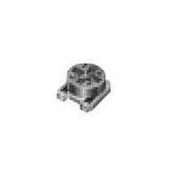
PVM4A203B01R00
Description
Trimmer Resistors - SMD 20K OHM SMD 4MM
Manufacturer
Murata
Series
PVM4r
Datasheet
1.PVZ3A503A01R00.pdf
(55 pages)
Specifications of PVM4A203B01R00
Lead Free Status / Rohs Status
Lead free / RoHS Compliant


!Note
• This PDF catalog is downloaded from the website of Murata Manufacturing co., ltd. Therefore, it’s specifications are subject to change or our products in it may be discontinued without advance notice. Please check with our
• This PDF catalog has only typical specifications because there is no space for detailed specifications. Therefore, please approve our product specifications or transact the approval sheet for product specifications before ordering.
sales representatives or product engineers before ordering.
!Note
1. Store in temperatures of -10 to +40 deg. C and
2. Do not store in or near corrosive gases.
3. Use within six months after delivery.
4. Open the package just before using.
5. Do not store under direct sunlight.
6. If you use the trimmer potentiometer in an
1. When using with partial load (rheostat), minimize
2. The maximum input voltage to a trimmer
1. Soldering
(1) Soldering condition
(2) To minimize mechanical stress when adjusting,
(3) The soldering iron should not come in contact
Notice (Operating and Storage Conditions)
relative humidity of 30-85%.
environment other than listed below, please
consult with a Murata factory representative prior
to using.
The trimmer potentiometer should not be used under
the following environmental conditions:
Notice (Rating)
the power depending on the resistance value.
potentiometer should not exceed (P•R)^1/2 or the
maximum operating voltage, whichever is smaller.
Notice (Soldering and Mounting)
Refer to the temperature profile.
If the soldering conditions are not suitable,
e.g., excessive time and/or excessive
temperature, the trimmer potentiometer may
deviate from the specified characteristics.
the trimmer potentiometer should be mounted onto
PCB without gap.
with the case of the trimmer potentiometer. If
such contact does occur, the trimmer
potentiometer may be damaged.
• Please read rating and !CAUTION (for storage, operating, rating, soldering, mounting and handling) in this catalog to prevent smoking and/or burning, etc.
• This catalog has only typical specifications because there is no space for detailed specifications. Therefore, please approve our product specifications or transact the approval sheet for product specifications before ordering.
2. Mounting
3. Cleaning
(1) Corrosive gaseous atmosphere
(2) In liquid
(3) Dusty/dirty atmosphere
(4) Direct sunlight
(5) Static voltage nor electric/magnetic fields
(6) Direct sea breeze
(7) Other variations of the above
(1) Use PCB hole to meet the pin of the trimmer
(2) Do not apply excessive force, preferably 9.8N
Isopropyl-alcohol and Ethyl-alcohol are applicable
solvents for cleaning. If you use any other types
of solvents, please consult with a Murata factory
representative prior to using.
(Ex. Chlorine gas, Hydrogen sulfide gas, Ammonia
gas, Sulfuric acid gas, Nitric oxide gas, etc.)
(Ex. Oil, Medical liquid, Organic solvent, etc.)
potentiometer. If the trimmer potentiometer
installs into insufficient PCB hole, the
trimmer potentiometer may be damaged by
mechanical stress.
max. (Ref. 1kgf) when the trimmer potentiometer
is mounted to the PCB.
PV12/PV37/PV36 Series Notice
R50E.pdf
43
11.1.17
7
Related parts for PVM4A203B01R00
Image
Part Number
Description
Manufacturer
Datasheet
Request
R

Part Number:
Description:
Murata Microblower 20x20 DCDC Driver Board - Samples Only
Manufacturer:
Murata
Part Number:
Description:
357-036-542-201 CARDEDGE 36POS DL .156 BLK LOPRO
Manufacturer:
Murata
Datasheet:
Part Number:
Description:
Manufacturer:
Murata
Datasheet:
Part Number:
Description:
Manufacturer:
Murata
Datasheet:
Part Number:
Description:
Manufacturer:
Murata
Datasheet:
Part Number:
Description:
Manufacturer:
Murata
Datasheet:
Part Number:
Description:
Manufacturer:
Murata
Datasheet:
Part Number:
Description:
Manufacturer:
Murata
Datasheet:
Part Number:
Description:
Manufacturer:
Murata
Datasheet:
Part Number:
Description:
BLM21BD751SN1On-Board Type (DC) EMI Suppression Filters
Manufacturer:
Murata
Datasheet:
Part Number:
Description:
BLM15AG100SN1On-Board Type (DC) EMI Suppression Filters
Manufacturer:
Murata
Datasheet:
Part Number:
Description:
NFE31PT222Z1E9On-Board Type (DC) EMI Suppression Filters
Manufacturer:
Murata
Datasheet:
Part Number:
Description:
Chip Coil
Manufacturer:
Murata
Datasheet:
Part Number:
Description:
Chip Coil
Manufacturer:
Murata
Datasheet: