28-505-110 Aries Electronics, 28-505-110 Datasheet
28-505-110
Manufacturer Part Number
28-505-110
Description
IC & Component Sockets PLCC TO PGA ADAPT
Manufacturer
Aries Electronics
Datasheet
1.28-505-111P.pdf
(1 pages)
Specifications of 28-505-110
Product
Various Socket Types
Number Of Positions / Contacts
28
Mounting Style
PCB
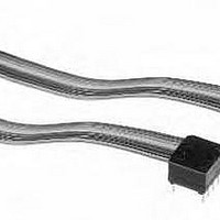
Features
Brass header pins, 10 color cable
Lead Free Status / Rohs Status
Lead free / RoHS Compliant
PRINTOUTS OF THIS DOCUMENT MAY BE OUT OF DATE AND SHOULD BE CONSIDERED UNCONTROLLED
FEATURES:
• Aries offers a wide array of DIP jumper configurations and wiring possibilities for all
• Reliable, electronically tested solder connections.
• Protective covers are ultrasonically welded on and
• 10-color cable allows for easy identification and tracing.
• Consult factory for jumper lengths under 2.000 [50.80].
SPECIFICATIONS:
• Header body and cover is black UL 94V-0 4/6 Nylon.
• Header pins are Brass, 1/2 hard.
• Standard Pin plating is 10 μ [.25μm] min. Gold per MIL-G-45204 over 50 μ [1.27μm]
• Optional Plating:
• Cable insulation is UL Style 2697 Polyvinyl Chloride (PVC).
• Laminate is clear PVC, self-extinguishing.
• .050 [1.27] pitch conductors are 28 AWG, 7/36 strand, Tinned Copper per ASTM B 33
• Cable current rating=1 Amp @ 10°C [50°F] above
• Cable voltage rating=300 Volts.
• Cable temperature rating=176°F [80°C].
• Cable capacitance=13.0 pf/ft. [42.7pf/meter] nominal
• Crosstalk: 10’ sample, 5 ns rise time with 2 lines driven. Near end=4.7%;
• Propagation delay=1.5 ns/ft. [4.9 ns/meter] nominal.**
• Insulation resistance=10 10 Ohms (10 ft. [3 meters] min.).
**Note: Applies to .050 [1.27] pitch cable only.
MOUNTING CONSIDERATIONS:
•Suggested PCB hole size=.033 ± .002 [.86 ±.05].
shown pin
reference
http://www.arieselec.com • info@arieselec.com
Numbers
your programming needs.
provide strain relief for cables.
min. Nickel per QQ-N-290.
“T” = 200μ” [5.08μm] min. Matte Tin per ASTM B545-97 over 50μ” [1.27μm] min.
Nickel per QQ-N-290.
“TL” = 200μ” [5.08μm] 90/10 Tin/Lead per MIL-T-10727 Type I over 50μ” [1.27μm]
min. Nickel per QQ-N-290.
(.039 [.99] pitch conductors are 26 AWG, 7/34 strand).
ambient.
@1 MHz.**
Far end=4.3% nominal.**
side for
SERIES
SERIES
only.
101
100
Series 100 thru 111 DIP Jumpers
“L” ± .125
“L” ± .125
**
additional information.
See Data Sheet No.
configurations and
Bristol, PA USA
TEL: (215) 781-9956
FAX: (215) 781-9845
All Dimensions: Inches [Millimeters]
Note: 10, 12, 18, 20, & 28
11007 for other
conductor jumpers do not
have numbers on covers.
“A”=(NO. OF CONDUCTORS X .050 [1.27) + .095 [2.41]
“B”=(NO. OF CONDUCTORS - 1) X .050 [1.27]
Centers “C”
.400 [10.16]
.600 [15.24]
.300 [7.62]
Ex: 2” = -002-
(min. length=2.”[50.80mm])
No. of conductors
Cable length in inches:
2.5” = -002.5-
.395 [10.03]
.495 [12.57]
.695 [17.65]
(see table)
Dim. “D”
Note: Aries specializes in custom design and production. In addition to the
standard products shown on this page, special materials, platings, sizes,
and configurations can be furnished, depending on quantities. Aries
reserves the right to change product specifications without notice.
ORDERING INFORMATION
abc
X X - X X X X - X X X X X X
Available Sizes
24, 28, 40
4 thru 20
22
Jumper
series
HEADER DETAIL
All tolerances ± .005[.13]
unless otherwise specified
T=Tin plated header pins
TL= Tin/Lead plated
TW=twisted pair cable
ST=stripped and Tin
STL= stripped and
Tin/Lead Dipped Ends
header pins
Dipped ends
(Series 106-111)
(Series 106-111)
Optional suffix:
REV. H
11006
Related parts for 28-505-110
Image
Part Number
Description
Manufacturer
Datasheet
Request
R

Part Number:
Description:
IC & Component Sockets PLCC TO PGA ADAPT
Manufacturer:
Aries Electronics
Datasheet:
Part Number:
Description:
IC & Component Sockets PLCC TO PGA ADAPT
Manufacturer:
Aries Electronics
Datasheet:

Part Number:
Description:
28-BIT SIGMA DELTA A/D IC
Manufacturer:
Analog Devices Inc
Datasheet:

Part Number:
Description:
IC ADC 10BIT HS 28-SSOP
Manufacturer:
NXP Semiconductors
Datasheet:

Part Number:
Description:
28 MODIV HSG COMP SR .100CL
Manufacturer:
TE Connectivity
Datasheet:

Part Number:
Description:
Row-to-Row DIP Adapter Socket
Manufacturer:
ARIES [Aries Electronics, Inc.]
Datasheet:
Part Number:
Description:
5-Pin PLCC Motorola MC68HC11E9-to-56-Pin SDIP Adapter
Manufacturer:
ARIES [Aries Electronics, Inc.]
Datasheet:
Part Number:
Description:
64-Pin DIP-to-PLCC 68-Pin Zilog Z80180 Adapter
Manufacturer:
ARIES [Aries Electronics, Inc.]
Datasheet:
Part Number:
Description:
RoHs/WEEE-Compliant SOIC-to-JEDEC TO Adapter
Manufacturer:
ARIES [Aries Electronics, Inc.]
Datasheet:
Part Number:
Description:
68-Pin PLCC-to-DIP 64-Pin Motorola MC68HC000 Adapter
Manufacturer:
ARIES [Aries Electronics, Inc.]
Datasheet:
Part Number:
Description:
Surface Mount-to-DIP JEDEC SOT-25, SOT-23A-6 Adapter
Manufacturer:
ARIES [Aries Electronics, Inc.]
Datasheet:
Part Number:
Description:
0.5mm 8- and 10-Pin
Manufacturer:
ARIES [Aries Electronics, Inc.]
Datasheet: