20-101-1131 Rabbit Semiconductor, 20-101-1131 Datasheet - Page 3
20-101-1131
Manufacturer Part Number
20-101-1131
Description
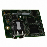
MODULE RCM4200 RABBITCORE
Manufacturer
Rabbit Semiconductor
Datasheet
1.20-101-1132.pdf
(134 pages)
Specifications of 20-101-1131
Module/board Type
MPU Core Module
Product
Microcontroller Modules
Core Processor
Rabbit 4000
Flash
512 KBytes
Operating Supply Voltage
3 to 3.6 V
Board Size
61 mm x 47 mm x 21 mm
Cpu Core
Rabbit 4000
For Use With/related Products
RCM4200
Lead Free Status / RoHS Status
Lead free / RoHS Compliant
Other names
316-1124


Chapter 1. Introduction
Chapter 2. Getting Started
Chapter 3. Running Sample Programs
Chapter 4. Hardware Reference
User’s Manual
1.1 RCM4200 Features ...............................................................................................................................2
1.2 Advantages of the RCM4200 ...............................................................................................................4
1.3 Development and Evaluation Tools......................................................................................................5
2.1 Install Dynamic C .................................................................................................................................7
2.2 Hardware Connections..........................................................................................................................8
2.3 Run a Sample Program .......................................................................................................................12
2.4 Where Do I Go From Here? ...............................................................................................................13
3.1 Introduction.........................................................................................................................................15
3.2 Sample Programs ................................................................................................................................16
4.1 RCM4200 Digital Inputs and Outputs ................................................................................................28
4.2 Serial Communication ........................................................................................................................35
4.3 Programming Cable ............................................................................................................................39
1.3.1 RCM4200 Development Kit .........................................................................................................5
1.3.2 Software ........................................................................................................................................6
1.3.3 Online Documentation ..................................................................................................................6
2.2.1 Step 1 — Prepare the Prototyping Board for Development..........................................................8
2.2.2 Step 2 — Attach Module to Prototyping Board............................................................................9
2.2.3 Step 3 — Connect Programming Cable ......................................................................................10
2.2.4 Step 4 — Connect Power ............................................................................................................11
2.3.1 Troubleshooting ..........................................................................................................................12
2.4.1 Technical Support .......................................................................................................................13
3.2.1 Use of Serial Flash ......................................................................................................................18
3.2.2 Serial Communication.................................................................................................................19
3.2.3 A/D Converter Inputs (RCM4200 only) .....................................................................................22
3.2.4 Real-Time Clock .........................................................................................................................25
4.1.1 Memory I/O Interface .................................................................................................................34
4.1.2 Other Inputs and Outputs ............................................................................................................34
4.2.1 Serial Ports ..................................................................................................................................35
4.2.2 Ethernet Port ...............................................................................................................................37
4.2.3 Programming Port .......................................................................................................................38
4.3.1 Changing Between Program Mode and Run Mode ....................................................................39
4.3.2 Standalone Operation of the RCM4200......................................................................................40
3.2.3.1 Downloading and Uploading Calibration Constants.......................................................... 23
4.2.1.1 Using the Serial Ports......................................................................................................... 36
T
ABLE OF
C
ONTENTS
15
27
1
7
Related parts for 20-101-1131
Image
Part Number
Description
Manufacturer
Datasheet
Request
R

Part Number:
Description:
COMPUTER SGL-BRD BL2500 29.4MHZ
Manufacturer:
Rabbit Semiconductor
Datasheet:

Part Number:
Description:
COMPUTER SGL-BRD BL2500 29.4MHZ
Manufacturer:
Rabbit Semiconductor
Datasheet:

Part Number:
Description:
DISPLAY GRAPHIC 12KEY PROG OP670
Manufacturer:
Rabbit Semiconductor
Datasheet:
Part Number:
Description:
DISPLAY GRAPHIC 12KEY ETH OP6700
Manufacturer:
Rabbit Semiconductor
Datasheet:

Part Number:
Description:
COMPUTER SINGLE-BOARD BL2030
Manufacturer:
Rabbit Semiconductor
Part Number:
Description:
COMPUTER SGL-BOARD ETH BL2010
Manufacturer:
Rabbit Semiconductor

Part Number:
Description:
MODULE OP6810 W/O ETH/MEM EXPANS
Manufacturer:
Rabbit Semiconductor
Datasheet:
Part Number:
Description:
COMPUTER SINGLE-BOARD BL2020
Manufacturer:
Rabbit Semiconductor
Part Number:
Description:
COMPUTER BL2010 W/FRICTION LOCK
Manufacturer:
Rabbit Semiconductor
Part Number:
Description:
COMPUTER BL2020 W/FRICTION LOCK
Manufacturer:
Rabbit Semiconductor
Part Number:
Description:
COMPUTER SGL-BRD BL2500 44.2MHZ
Manufacturer:
Rabbit Semiconductor
Datasheet:
Part Number:
Description:
COMPUTER SGL-BOARD FULL BL2000
Manufacturer:
Rabbit Semiconductor

Part Number:
Description:
COMPUTER SINGLE-BOARD BL2110
Manufacturer:
Rabbit Semiconductor

Part Number:
Description:
COMPUTER SGL-BRD 29.4MHZ BL2610
Manufacturer:
Rabbit Semiconductor
Datasheet:
Part Number:
Description:
INTERFACE OP6800 512K FLASH&SRAM
Manufacturer:
Rabbit Semiconductor
Datasheet: