DLP-245PB-G DLP Design Inc, DLP-245PB-G Datasheet
DLP-245PB-G
Specifications of DLP-245PB-G
Available stocks


Related parts for DLP-245PB-G


DLP-245PB-G Summary of contents
Page 1
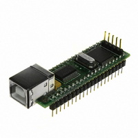
... USB / Microcontroller Module (Lead-Free) The DLP-245PB-G combines the same USB interface used in the DLP-USB245M-G module with a Microchip PIC microcontroller to form a rapid development tool. The 16F877A microcontroller is preprogrammed with basic functionality for accessing the port pins and can be reprogrammed with user hex code via a 5-pin header using a device programmer (purchased separately) ...
Page 2
Royalty-free device drivers eliminate the need for USB driver development in most cases • USB bulk or isocronous data-transfer modes • Required 5V supply can be taken directly from the USB port or supplied by user electronics • USB ...
Page 3
... COM (RS-232) port. In addition to VCP drivers, FTDI's D2XX direct drivers for Windows offer an alternative solution to the VCP drivers that allow application software to interface with the DLP-245PB-G using a DLL instead of a virtual com port. The architecture of the D2XX drivers consists of a Windows WDM V2 ...
Page 4
... EEPROM WRITE UTILITY The DLP-245PB-G has the option to accept manufacturer-specific information that is written into on-board EEPROM memory. Parameters that can be programmed include the VID and the PID identifiers, the manufacturer's product string, and a serial number. ...
Page 5
... Download the DLL (D2XX) version of the device drivers from either dlpdesign.com or ftdichip.com. Unzip the drivers onto a blank floppy disk or into a folder on the hard drive. 2. The DLP-245PB-G can be configured to receive its operating power from the USB port or from user electronics. Pins 18, 19, and 20 allow for this configuration. (Refer to the Pinout Description in the next section for a detailed description of the DLP-245PB-G electrical interface ...
Page 6
... Features include the ability to read and write individual port pins as well as 8-bit port reads and writes. The firmware in the DLP-245PB-G also provides access to the 16F877A’s A/D converter, EEPROM memory, and communications with digital temperature-sensing devices. Commands sent to the Token I/O firmware must adhere to a specific communications protocol. ...
Page 7
... The source code for the Token I/O firmware (developed for the CCS C compiler) is available as a free download upon purchase and receipt of the hardware. Example Visual C++ source code (for Windows 98/2000/XP) for communicating with the DLP-245PB-G via the Token I/O firmware is also available for download. The windows source code also contains the port pin definitions listed above ...
Page 8
... This function will select the source for the A/D conversion clock. (Refer to the datasheet for the 16F877A for a detailed explanation of the conversion clock.) Example: 0x3, 0xA8, 0x0, 0x7, 0xAC – Sets all available A/D inputs on the DLP-245PB-G to analog mode (0x0) and selects the internal A/D clock (0x7). V2.3 ...
Page 9
A/D Conversion Parameters: Analog Port Number – Selects the analog port for the A/D conversion. Returns: 2 Bytes: The 10-bit voltage data; LSB first. Function: This function will set the channel for the A/D conversion, pause 10uS, perform ...
Page 10
DS18S20 Start Convert Parameters: Port Pin – Selects the microcontroller port pin on the 16F877A to be used for communication with the DS18B20 temperature sensor. Returns: 1 Byte: A single byte indicating the result of trying to reset ...
Page 11
Reserved 0xAF – Loopback Parameters: Data byte – The byte of data to be looped back to the host. Returns: 1 Byte: The data byte written. Function: This function will echo the specified byte of data back to ...
Page 12
... TABLE 1: DLP-245PB-G PINOUT DESCRIPTION Pin # Description 1 GROUND 2 E0 (I/O) Port Pin E0 connected to the 16F877A microcontroller. A/D Channel (I/O) Port Pin A0 connected to the 16F877A microcontroller. A/D Channel (I/O) Port Pin A1 connected to the 16F877A microcontroller. A/D Channel 1. A2 (I/O) Port Pin A2 connected to the 16F877A microcontroller. A/D Channel 2. ...
Page 13
... PORTVCC if the module powered by the USB port (typical configuration). 20 PORTVCC (Out) Power from USB port. Connect to EXTVCC if module powered by the USB port (typical configuration). 500mA is the maximum current available to the DLP-245PB-G and target electronics if the USB device is configured for high power. 21 DB7 (I/O) Line 7 of the data bus between the 16F877A and the FT245RL USB-FIFO ...
Page 14
... This product and its documentation are supplied on an as-is basis, and no warranty as to their suitability for any particular purpose is either made or implied. DLP Design will not accept any claim for damages whatsoever arising as a result of use or failure of this product. Your statutory rights are not affected ...
Page 15
... This document provides preliminary information that may be subject to change without notice. CONTACT INFORMATION DLP Design 1605 Roma Lane Allen, TX 75013 Phone: 469-964-8027 Fax: 415-901-4859 Email: support@dlpdesign.com Internet: http://www.dlpdesign.com V2.3 15 Page 15 of February 2007 ...
Page 16
AGND 7 GND 18 GND 21 GND 26 TEST 4 VCCIO Vss VDD 6 7 Vss VDD ...