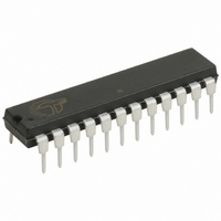
CY7C63743-PXC Cypress Semiconductor Corp, CY7C63743-PXC Datasheet - Page 25

CY7C63743-PXC
Manufacturer Part Number
CY7C63743-PXC
Description
IC MCU 8K USB/PS2 LS 24DIP
Manufacturer
Cypress Semiconductor Corp
Series
enCoRe™r
Specifications of CY7C63743-PXC
Applications
USB Microcontroller
Core Processor
M8B
Program Memory Type
OTP (8 kB)
Controller Series
CY7C637xx
Ram Size
256 x 8
Interface
PS2, USB
Number Of I /o
16
Voltage - Supply
4 V ~ 5.5 V
Operating Temperature
0°C ~ 70°C
Mounting Type
Through Hole
Package / Case
24-DIP (0.300", 7.62mm)
Lead Free Status / RoHS Status
Lead free / RoHS Compliant
Other names
428-1621
Available stocks
Company
Part Number
Manufacturer
Quantity
Price
Company:
Part Number:
CY7C63743-PXC
Manufacturer:
TI
Quantity:
12 749
19.0
Four 8-bit capture timer registers provide both rising- and
falling-edge event timing capture on two pins. Capture Timer
A is connected to Pin 0.0, and Capture Timer B is connected
to Pin 0.1. These can be used to mark the time at which a rising
or falling event occurs at the two GPIO pins. Each timer will
The four Capture Timer Data Registers are read-only, and are
shown in Figure 19-2 through Figure 19-5.
Out of the 12-bit free running timer, the 8-bit captured in the
Capture Timer Data Registers are determined by the Prescale
Bit [2:0] in the Capture Timer Configuration Register
(Figure 19-7).
.
Document #: 38-08022 Rev. *B
Capture A Rising Int Enable
Capture A Falling Int Enable
Capture B Rising Int Enable
Capture B Falling Int Enable
Bit 0, Reg 0x44
Bit 1, Reg 0x44
Bit 2, Reg 0x44
Bit 3, Reg 0x44
Timer Capture Registers
GPIO
P0.0
GPIO
P0.1
First Edge Hold
Bit 7, Reg 0x44
Rising
Edge
Detect
Falling
Edge
Detect
Rising
Edge
Detect
Falling
Edge
Detect
Free-running Timer
11
FOR
FOR
10
Figure 19-1. Capture Timers Block Diagram
9
Prescaler
8
Mux
7
6
capture eight bits of the free-running timer into its Capture
Timer Data Register if a rising or falling edge event that
matches the specified rising or falling edge condition at the pin.
A prescaler allows selection of the capture timer tick size.
Interrupts can be individually enabled for the four capture
registers. A block diagram is shown in Figure 19-1.
Read/Write
5
Bit Name
Figure 19-2. Capture Timer A-Rising, Data Register
Reset
Bit #
Timer A Rising Edge Time
Timer A Falling Edge Time
Timer B Rising Edge Time
Timer B Falling Edge Time
8-bit Capture Registers
4
3
R
7
0
2
Capture Timer A Interrupt Request
Capture Timer B Interrupt Request
1
R
6
0
(Address 0x40)
Capture A Rising Data
0
R
5
0
R
4
0
R
3
0
1 MHz
Clock
CY7C63722
CY7C63723
CY7C63743
R
2
0
Page 25 of 49
R
1
0
R
0
0


