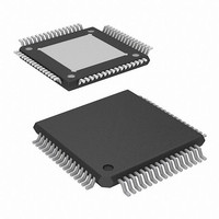
XS1-L01A-LQ64-I5 XMOS, XS1-L01A-LQ64-I5 Datasheet - Page 8

XS1-L01A-LQ64-I5
Manufacturer Part Number
XS1-L01A-LQ64-I5
Description
IC MPU 32BIT SINGLE CORE 64LQFP
Manufacturer
XMOS
Datasheet
1.XS1-L01A-LQ64-C4.pdf
(24 pages)
Specifications of XS1-L01A-LQ64-I5
Processor Type
XCore 32-Bit
Speed
500MHz
Voltage
0.95 V ~ 1.05 V
Package / Case
64-LQFP Exposed Pad, 64-eLQFP, 64-HLQFP
Lead Free Status / RoHS Status
Lead free / RoHS Compliant
Features
-
Mounting Type
-
Other names
880-1030
XS1-L1 64LQFP Datasheet (2.1)
When booting the XS1-L1 device from a SPI interface, the SPI device must be connected
Bits [1:0] control the PLL boot mode according to the following table:
NOTE: If secure boot from OTP is enabled by programming the OTP, the boot source
specified on the MODE[3:2] pins is ignored. For further details on booting XCores
see the
DEBUG This pin is used to synchronize the debugging of multiple XS1 devices.
RST_N Active low asynchronous-assertion global reset signal. At power-up, this pin
3.3 SPI Interface
to the XS1-L1 as follows:
MODE3
0
0
1
1
MODE1
0
0
1
1
Pin Name
X0D0
X0D1
X0D10
X0D11
This pin can operate in both output and input mode. In output mode and
when configured to do so, DEBUG is driven low by the device when the XCore
processor hits a debug break point. Prior to this point the pin will be tri-stated.
In input mode and when configured to do so, driving this pin low will put the
XCore into debug mode. Software can set the behavior of the XCore based on
this pin. This pin should have an external pull up of 4K7 ohms.
must be activated for at least 5us after the power supplies are stable to ensure
reliable booting. Following a reset the PLL re-establishes lock after which the
device boots up according to the boot mode (see MODE).
XS1-L System
MODE2
0
1
0
1
MODE0
0
1
0
1
Pin ID
16
15
1
64
Specification.
Boot Source
None - Device will wait to be booted (via JTAG)
Reserved
XMOS Link B
SPI
PLL Multiplier Ratio
30.75
4
8.3333
20
SPI Signal
MISO
SS
SCLK
MOSI
www.xmos.com
Description
Data - Master In Slave Out
Slave Select
Clock
Data - Master Out Slave In
PLL reference clk
4.22 to 13 MHz
21.66 to 100 MHz
10.4 to 48 MHz
4.33 to 20 MHz
Boot Frequency
130 to 399.75 MHz
86.66 to 400 MHz
86.66 to 400 MHz
86.66 to 400 MHz
8/24


