RK1-L-24V Panasonic, RK1-L-24V Datasheet
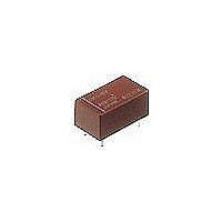
Low Signal Relays - PCB 1.5 GHz High Frequen 1 Coil Latching

RK1-L-24V

Manufacturer Part Number
RK1-L-24V
Description
Low Signal Relays - PCB 1.5 GHz High Frequen 1 Coil Latching
Manufacturer
Panasonic
Datasheet

Specifications of RK1-L-24V

Contact Form
1 Form C
Coil Voltage
24 VDC
Coil Current
8.3 mA
Coil Type
Single Latching
Power Consumption
200 mW
Contact Carry Current
500 mA
Termination Style
Solder Terminal
Isolation
60 dB at 1.5 GHz
Insertion Loss
0.3 dB at 1.5 GHz
Maximum Switching Current
500 mA
Contact Rating
500 mA
Lead Free Status / Rohs Status
Lead free / RoHS Compliant

Available stocks

Company
Part Number
Manufacturer
Quantity
Price
Part Number:
RK1-L-24V
Manufacturer:
Panasonic
Quantity:
12 000
ORDERING INFORMATION
TYPES
1. Standard type
Standard packing: 50 pcs. in an inner package; 500 pcs. in an outer package
Contact arrangement
1:
1R:
Operating function
Nil:
L:
L2:
Coil voltage, DC
3, 4.5, 5, 6, 9, 12, 24 V
Notes: 1. For transistor drive with 5 V circuits, we recommend the 4.5 V type in order to take into account voltage drops.
Compliance with RoHS Directive
arrangement
1 Form C
Contact
Standard contact type
Reversed contact type
Single side stable
1 coil latching
2 coil latching
2. No part number distinguishment on impedance in RK relays.
Nominal coil voltage
12 V DC
24 V DC
3 V DC
4.5V DC
5 V DC
6 V DC
9 V DC
All Rights Reserved © COPYRIGHT Panasonic Electric Works Co., Ltd.
RK
Single side stable type
FEATURES
1. Excellent high frequency
2. High sensitivity in small size
3. Sealed construction for automatic
4. Reversed contact types and
Impedance
Impedance
RK1-3V
RK1-4.5V
RK1-5V
RK1-6V
RK1-9V
RK1-12V
RK1-24V
Part No.
characteristics
Size: 20.2 × 11.2 × 9.7 mm
Nominal power consumption:
200 mW (single side stable type, 1 coil
latching)
cleaning
latching types (1 coil latching/2 coil
latching) are also available
(Initial)
(Initial)
50Ω
75Ω
MICROWAVE RELAYS
.795 × .441 × .382 inch
V.S.W.R. (Max.)
Insertion loss
(dB. Max.)
Isolation
(dB. Min.)
V.S.W.R. (Max.)
Insertion loss
(dB. Max.)
Isolation
(dB. Min.)
1.5 GHz
1.5 (at 900 MHz)
0.3 (at 900 MHz)
60 (at 1.5 GHz)
1.2 (at 900 MHz)
0.2 (at 900 MHz)
60 (at 1.5 GHz)
1 coil latching type
RK1-L-3V
RK1-L-4.5V
RK1-L-5V
RK1-L-6V
RK1-L-9V
RK1-L-12V
RK1-L-24V
Part No.
TYPICAL APPLICATIONS
• Audio visual equipment
• Communication equipment
• Instrumentation
If you wish to use in applications with low
level loads or with high frequency
switching, please consult us.
Broadcast satellite tuners VCRs,
CATVs, TVs
Automobile telephones, maritime
telephones, emergency and disaster
prevention communications, PCM
switches
Testing equipment, measuring
equipment
RK RELAYS
2 coil latching type
RK1-L2-3V
RK1-L2-4.5V
RK1-L2-5V
RK1-L2-6V
RK1-L2-9V
RK1-L2-12V
RK1-L2-24V
Part No.
RK

Related parts for RK1-L-24V

RK1-L-24V Summary of contents

Page 1

... Instrumentation Testing equipment, measuring equipment If you wish to use in applications with low level loads or with high frequency switching, please consult us. 2 coil latching type Part No. Part No. RK1-L-3V RK1-L2-3V RK1-L-4.5V RK1-L2-4.5V RK1-L-5V RK1-L2-5V RK1-L-6V RK1-L2-6V RK1-L-9V RK1-L2-9V RK1-L-12V RK1-L2-12V RK1-L-24V RK1-L2-24V RK ...

Page 2

... All Rights Reserved © COPYRIGHT Panasonic Electric Works Co., Ltd. 1 coil latching type 2 coil latching type Part No. RK1R-L-3V RK1R-L2-3V RK1R-L-4.5V RK1R-L2-4.5V RK1R-L-5V RK1R-L2-5V RK1R-L-6V RK1R-L2-6V RK1R-L-9V RK1R-L2-9V RK1R-L-12V RK1R-L2-12V RK1R-L-24V RK1R-L2-24V Coil resistance Nominal operating power 45Ω 101Ω 125Ω 180Ω ...

Page 3

... Note: * The upper operation ambient temperature limit is the maximum temperature that can satisfy the coil temperature rise value. Refer to [6] AMBIENT ENVIRONMENT in GENERAL APPLICATION GUIDELINES. REFERENCE DATA 1.-(1) High frequency characteristics (Impedance 75Ω) Sample: RK1-12V Measuring method: Measured with HP network analyzer (HP8753C) • V.S.W.R. characteristics 2.0 1 ...

Page 4

... Insertion loss characteristics 0 0.2 0.4 COM-NO 0.6 COM-NC 0.8 1.0 300kHz 1.5GHz Frequency 3.-(1) Operate/Release time (Single side stable) Sample: RK1-12V; No. of samples Operate time Release time 0 80 100 120 Voltage applied to coil, %V 4.-(2) Mechanical life test (Latching) Sample: RK1-L2-12V No ...

Page 5

... ON condition 5 10 .197 .394 Inter-relay distance, (mm, inch) DIMENSIONS (mm inch) CAD Data All Rights Reserved © COPYRIGHT Panasonic Electric Works Co., Ltd. 8.-(2) Influence of adjacent mounting Sample: RK1-12V; No. of samples OFF Pick-up voltage 0 0 OFF –10 OFF condition 10 Drop-out voltage 0 –10 ON condition ...

Page 6

... This causes problems such as sticking of movable parts or operational time lags. All Rights Reserved © COPYRIGHT Panasonic Electric Works Co., Ltd. 4) Low temperature, low humidity environments The plastic becomes brittle if the relay is exposed to a low temperature, low humidity environment for long periods of time ...

Related keywords