G6S-2G-TR DC5 Omron, G6S-2G-TR DC5 Datasheet - Page 10
G6S-2G-TR DC5
Manufacturer Part Number
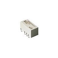
G6S-2G-TR DC5
Description
Low Signal Relays - PCB SMT Relay Tape & Reel
Manufacturer
Omron
Series
G6Sr
Datasheet
1.G6S-2_DC5.pdf
(12 pages)
Specifications of G6S-2G-TR DC5
Contact Form
2 Form C
Coil Voltage
5 VDC
Coil Type
Non-Latching
Power Consumption
140 mW
Termination Style
Solder Pad
Lead Free Status / Rohs Status
Lead free / RoHS Compliant
Other names
BY DC5 G6S2GTR G6S2GTRDC5BYOMR OMR


Precautions
• Use a DC power supply with 5% or less ripple factor to operate the coil.
• Do not use the G6S where subject to strong external magnetic fields.
• Do not use the G6S where subject to magnetic particles or excessive
• Do not reverse the polarity of the coil (+, −).
■ Correct use
Long-term Continuously ON Contacts
Using the Relay in a circuit where the Relay will be ON continuously
for long periods (without switching) can lead to unstable contacts
because the heat generated by the coil itself will affect the insulation,
causing a film to develop on the contact surfaces. We recommend
using a latching relay (magnetic-holding relay) in this kind of circuit. If
a single-side stable model must be used in this kind of circuit, we rec-
ommend using a fail-safe circuit design that provides protection
against contact failure or coil burnout.
Relay Handling
Use the Relay as soon as possible after opening the moisture-proof
package. If the Relay is left for a long time after opening the mois-
ture-proof package, the appearance may suffer and seal failure may
occur after the solder mounting process. To store the Relay after
opening the moisture-proof package, place it into the original pack-
age and sealed the package with adhesive tape.
When washing the product after soldering the Relay to a PCB, use a
water-based solvent or alcohol-based solvent, and keep the solvent
temperature to less than 40°C. Do not put the Relay in a cold clean-
ing bath immediately after soldering.
104
amounts of dust.
Low Signal Relay
G6S
• Latching types are delivered in the reset position. We recommend
• Do not drop the G6S or otherwise subject it to excessive shock.
• Remove the relay from the packing immediately prior to usage.
G6S (K) (-U) -2 Soldering
• Soldering temperature: Approx. 250°C (At 260°C if the DWS
• Soldering time: Approx. 5 s max. (Approx. 2 s for the first time and
• Be sure to adjust the level of the molten solder so that the solder
Claw Securing Force During Automatic Mounting
During automatic insertion of Relays, be sure to set the securing
force of each claw to the following so that the Relay’s characteristics
will be maintained.
Dimension A: 1.96 N max.
Dimension B: 4.90 N max.
Dimension C: 1.96 N max.
A
that a reset voltage be applied in advance to start operation.
method is used.)
approx. 3 s for the second time if the DWS method is used.)
will not overflow onto the PCB.
C
B
Related parts for G6S-2G-TR DC5
Image
Part Number
Description
Manufacturer
Datasheet
Request
R

Part Number:
Description:
G6S-2GLow Signal Relay
Manufacturer:
Omron Corporation
Datasheet:

Part Number:
Description:
RELAY LOW SIGNAL SMD
Manufacturer:
Omron
Datasheet:

Part Number:
Description:
Low Signal Relays - PCB J LEADS DPDT 24VDC
Manufacturer:
Omron
Datasheet:
Part Number:
Description:
Low Signal Relays - PCB J LEADS DPDT 5VDC
Manufacturer:
Omron
Datasheet:
Part Number:
Description:
Low Signal Relays - PCB J LEADS DPDT 12VDC
Manufacturer:
Omron
Datasheet:

Part Number:
Description:
SMT Relay
Manufacturer:
Omron
Datasheet:
Part Number:
Description:
SMT TAPE AND REEL RELAY
Manufacturer:
Omron
Datasheet:
Part Number:
Description:
SMT TAPE AND REEL RELAY
Manufacturer:
Omron
Datasheet:
Part Number:
Description:
SMT TAPE AND REEL RELAY
Manufacturer:
Omron
Datasheet:
Part Number:
Description:
SMT Tape And Reel Relay
Manufacturer:
Omron
Datasheet:
Part Number:
Description:
EN60950 SMT Relay Tape & Reel
Manufacturer:
Omron
Datasheet:
Part Number:
Description:
EN60950 SMT Relay Tape & Reel
Manufacturer:
Omron
Datasheet:
Part Number:
Description:
EN60950 SMT Relay Tape & Reel
Manufacturer:
Omron
Datasheet:
Part Number:
Description:
EN60950 SMT Relay Tape & Reel
Manufacturer:
Omron
Datasheet:
Part Number:
Description:
SMT Relay
Manufacturer:
Omron
Datasheet: