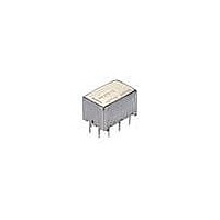
ARJ204H Panasonic, ARJ204H Datasheet - Page 3

ARJ204H
Manufacturer Part Number
ARJ204H
Description
Low Signal Relays - PCB 2 Form C, 4.5VDC 10mA 10VDC 50ohms
Manufacturer
Panasonic
Datasheet
1.ARJ22A12.pdf
(5 pages)
Specifications of ARJ204H
Contact Form
2 Form C
Coil Voltage
4.5 VDC
Coil Current
44.4 mA
Coil Type
Single Side Stable
Power Consumption
200 mW
Contact Carry Current
300 mA
Termination Style
Solder Terminal
Isolation
35 dB at 5 GHz
Insertion Loss
0.5 dB at 5 GHz
Maximum Switching Current
300 mA
Contact Rating
300 mA
Lead Free Status / Rohs Status
Lead free / RoHS Compliant
Available stocks
Company
Part Number
Manufacturer
Quantity
Price
Company:
Part Number:
ARJ204H
Manufacturer:
Panasonic
Quantity:
12 000
REFERENCE DATA
1. High frequency characteristics
Sample: ARJ20A12
Measuring method: Measured with HP network analyzer (HP8510C).
• V.S.W.R. characteristics
DIMENSIONS
1. Standard PC board terminal
2. Surface mount terminal
Note: Please consult us regarding recommended PC board patterns.
CAD Data
CAD Data
2.0
1.9
1.8
1.7
1.6
1.5
1.4
1.3
1.2
1.1
1.0
45MHz
Frequency
10.4
.409
(mm inch)
10.4
.409
6.36
.250
6.36
.250
5GHz
3.50
.138
0.50
.020
0.40
.016
0.50
.020
0.50
.020
0.20
.008
12.70
11.40
11.40
10.6
.417
12.2
.480
14.0
.551
8.89
.350
.500
.449
10.6
.417
8.89
.350
12.2
.480
14.0
.551
15.0
.591
.449
All Rights Reserved © COPYRIGHT Panasonic Electric Works Co., Ltd.
8GHz
The CAD data of the products with a
0.40
.016
0.20
.008
0.15
.006
0.20
.008
24 ribs should be soldered
0.50
.020
A
24 ribs should be soldered
0.50
.020
with PC board ground.
3.81
.150
A
with PC board ground.
• Insertion loss characteristics
1All bottom surface of the base should be
(without D.U.T. board’s loss)
1All bottom surface of the base should be
9.00
.354
7.62
.300
touched closely or soldered with PC board
ground.
touched closely or soldered with PC board
ground.
9.00
.354
10.0
.394
0.5
1.0
1.5
2.0
2.5
3.0
0.50
.020
3.81
.150
General tolerance: ±0.3
General tolerance: ±0.3
0
45MHz
8.20
.323
8.20
.323
Coplanarity of terminals
3Better HF characteristics
3Better HF characteristics
may be obtained when this
portion is soldered with
PC board ground.
may be obtained when this
portion is soldered with
PC board ground.
Expansion of A:
Expansion of A
& ribs & base
0 to .008
(Typical: 0.1)
(Typical: .004)
0 to 0.2
0 to .008
(Typical: 0.1)
(Typical: .004)
0 to 0.2
Frequency
CAD Data
5GHz
±.012
±.012
mark can be downloaded from: http://panasonic-electric-works.net/ac
8GHz
Direction
indication
Direction
indication
(Deenergized condition)
(Deenergized condition)
Single side stable
Single side stable
NC
NC
10
10
9
9
• Isolation characteristics
+
+
8
1
1
8
Schematic (Bottom view)
Com
Com
Com
Com
7
2
2
Schematic (Top view)
7
10
20
30
40
50
60
70
80
0
6
3
45MHz
3
6
–
–
5
4
4
5
NO
NO
Between contact sets
Between open contact
NC
NC
(Reset condition)
(Reset condition)
Frequency
10
10
9
9
2 coil latching
2 coil latching
5GHz
+
+
+
+
RJ (ARJ)
1
8
8
1
Com
Com
Com
Com
7
2
2
7
3
6
6
3
–
–
–
–
4
5
5
4
8GHz
NO
NO


