JL15SKSDDP2-RO NKK Switches, JL15SKSDDP2-RO Datasheet - Page 2
JL15SKSDDP2-RO
Manufacturer Part Number
JL15SKSDDP2-RO
Description
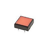
Tactile & Jog Switches SPST OFF-(ON) 50mA AMBER LED/AMBER ACT.
Manufacturer
NKK Switches
Series
JLr
Datasheet
1.JL15SKSBFP2.pdf
(4 pages)
Specifications of JL15SKSDDP2-RO
Operating Force
3 N
Actuator
Square
Contact Rating
50 mAmps at 24 VoltsDC
Ground Terminal
No
Contact Form
SPST
Switch Function
OFF - (ON)
Termination Style
Straight PC
Mounting Direction
Straight
Body Size
22 mm L x 22 mm W x 7.85 mm H
Features
Distinctive design allows full face illumination in extra low profile of 7.85 mm from PCB to top of switch; amber LED; black housing
Mounting Style
Through Hole
Operating Temperature Range
- 25 C to + 50 C
Travel
0.75 mm
Lead Free Status / Rohs Status
Lead free / RoHS Compliant
Other names
633-JL15SKSDDP2 JL-15SKSYYP2 JL15SKSDDP2


Distinctive
Bright, full face illumination with choice of red, green, or amber LEDs.
Multiple LED arrays and interior reflectors enhance illumination
of the large, .75” (19mm) square actuator surface.
Distinctive design allows full face illumination
in extra low profile of 0.31” (7.85mm) from
PCB to top of switch.
Dome contact gives crisp tactile and audible
feedback with short stroke and assures high
reliability and long life of 1,000,000 operations.
Crimped terminals provide a spring type action to ensure
secure mounting and prevent dislodging during the soldering process.
Streamlined housing dimensions provide for compact, side-by-side
mounting on a standard grid.
Terminal spacing conforms to standard .100” (2.54mm) PCB grid.
Illuminated Ultra-Thin Tactiles
4
3
1
These single pole, single throw switches can be used in a key-
board matrix and, using strapped terminals, achieve a com-
mon bus electrical configuration on a single-sided PC board.
4
1
7
A
5
2
2
5
8
0
9
7
Common Bus Matrix
3
9
B
6
13
10
12
11
6
8
Characteristics
3
4
5
6
8
9
0
A
B
1
2
7
1 2 3 4 5 6 7 8 9 10 11 12 13
P C T e r m i n a t i o n s
Red = PCB Trace
= ON
Black = Switch Circuit
www.nkk.com
5
These single pole, single throw switches can be
arranged on a single-sided PC board matrix
with strapped terminals to achieve an X-Y type
electrical interconnection.
1
4
7
A
4
2
5
8
0
3
X-Y Matrix
B
3
6
9
2
6
7
1
Series JL
Actual Size
PC Ter m i na t i ons
2
3
4
5
6
7
8
9
0
A
B
1
1 2 3 4 5 6 7
= ON
J47
J
Related parts for JL15SKSDDP2-RO
Image
Part Number
Description
Manufacturer
Datasheet
Request
R

Part Number:
Description:
Rocker Switches & Paddle Switches High In-rush Rated Rocker Switch
Manufacturer:
NKK Switches
Datasheet:
Part Number:
Description:
Rocker Switches & Paddle Switches High In-rush Rated Rocker Switch
Manufacturer:
NKK Switches
Datasheet:
Part Number:
Description:
Rocker Switches & Paddle Switches High In-rush Rated Rocker Switch
Manufacturer:
NKK Switches
Datasheet:
Part Number:
Description:
Rocker Switches & Paddle Switches High In-rush Rated Rocker Switch
Manufacturer:
NKK Switches
Datasheet:

Part Number:
Description:
Pushbutton Switches SPST ON(OFF) 15/32'
Manufacturer:
NKK Switches
Datasheet:

Part Number:
Description:
Pushbutton Switches SPST OFF(ON) 15/32'
Manufacturer:
NKK Switches
Datasheet:

Part Number:
Description:
Pushbutton Switches ON(OFF) NORM CLSD 3A RED PLNGR LUG 15/32
Manufacturer:
NKK Switches
Datasheet:

Part Number:
Description:
Pushbutton Switches SPDT ON-(ON)
Manufacturer:
NKK Switches
Datasheet:

Part Number:
Description:
Pushbutton Switches ON-(ON) RND BUSH MNT RED LED RED/RED CAP
Manufacturer:
NKK Switches
Datasheet:
Part Number:
Description:
Pushbutton Switches SPST ON-(OFF) STRT
Manufacturer:
NKK Switches
Datasheet:
Part Number:
Description:
Pushbutton Switches OFF(ON) NORM OPEN 3A RED CAP LUG 15/32
Manufacturer:
NKK Switches
Datasheet:
Part Number:
Description:
Pushbutton Switches ILLUM PUSHBUTTON SPDT
Manufacturer:
NKK Switches
Datasheet:
Part Number:
Description:
Pushbutton Switches OFF(ON) NORM OPEN 3A BLK CAP LUG 15/32
Manufacturer:
NKK Switches
Datasheet:
Part Number:
Description:
Pushbutton Switches SPST NO Metric Thrd Blk Plunge w/Blu Cap
Manufacturer:
NKK Switches
Datasheet:
Part Number:
Description:
Pushbutton Switches SPST OFF-(ON) NO 3A
Manufacturer:
NKK Switches
Datasheet: