EC2A04N-H Cincon, EC2A04N-H Datasheet
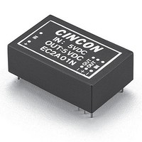
EC2A04N-H
Manufacturer Part Number
EC2A04N-H
Description
DC/DC Converters & Regulators 1.5W 5V +/-12V +/-62mA DIP-24
Manufacturer
Cincon
Series
EC2ANr
Datasheet
1.EC2A04N-H.pdf
(1 pages)
Specifications of EC2A04N-H
Product
Isolated
Output Power
0.74 W
Input Voltage Range
4.5 V to 5.5 V
Input Voltage (nominal)
5 V
Number Of Outputs
2
Output Voltage (channel 1)
12 V
Output Current (channel 1)
62 mA
Output Voltage (channel 2)
- 12 V
Output Current (channel 2)
62 mA
Isolation Voltage
3 KV
Package / Case Size
DIP
Output Voltage
12 V
Lead Free Status / Rohs Status
Lead free / RoHS Compliant
E C 2 A N
S
1.0-1.5 WATT,
UNREGULATED
DC-DC CONVERTERS
• 1-1.5W Output Power
• Unregulated Outputs
• DIP-24 / SMD Package
NUMBER
EC2A01N
EC2A02N
EC2A03N
EC2A04N
EC2A05N
EC2A11N
EC2A12N
EC2A13N
EC2A14N
EC2A15N
MODEL
E
VOLTAGE
12 VDC
5 VDC
INPUT
R
I
±12 VDC
±15 VDC
±12 VDC
±15 VDC
VOLTAGE
12 VDC
15 VDC
12 VDC
15 VDC
OUTPUT
5 VDC
5 VDC
E
Features
CURRENT
125 mA
100 mA
±62 mA
±50 mA
220 mA
125 mA
100 mA
±62 mA
±50 mA
OUTPUT
220mA
S
• Efficiency to 70%
• Input Voltage 5V & 12V
• Pi Input Filter
NO LOAD
115 mA
115 mA
115 mA
115 mA
115 mA
45 mA
45 mA
45 mA
45 mA
45 mA
INPUT CURRENT
FULL LOAD
330 mA
420 mA
420 mA
420 mA
420 mA
120 mA
165 mA
165 mA
165 mA
165 mA
DIP-24
DIP-24
DIP-24
DIP-24
DIP-24
DIP-24
DIP-24
DIP-24
DIP-24
DIP-24
CASE
All Specifications Typical At Nominal Line, Full Load and 25˚C Unless Otherwise Noted.
All Specifications Typical At Nominal Line, Full Load and 25˚C Unless Otherwise Noted.
CASE A
NOTE:Pin Size is 0.02” Inch (0.5mm) DIA
All Dimensions In Inches(mm)
Tolerance
INPUT SPECIFICATIONS:
Input Voltage Range.............................................................................±10%
Input Filter.............................................................................................Pi Type
OUTPUT SPECIFICATIONS:
Voltage Accuracy.......................................................................±3.0% max.
Ripple and Noise, 20MHz BW
Short Circuit Protection..............................................................Momentary
Line Regulation
Load Regulation
All Other Models....................................................................................±6.0%
GENERAL SPECIFICATIONS:
Efficiency..........................................................................................60%~80%
Isolation Capacitance...........................................................................30pF
Isolation Resistance..........................................................................10
Switching Frequency...................................................................20KHz, min
Operating Ambient Temperature Range ...........................-25˚C to +71˚C
De-rating, Above 71˚C(Plastic Case)........Linearly to Zero power at 95˚C
De-rating, Above 71˚C (Copper Case)…Linearly to Zero power at 100˚C
Case Temperature (Plastic case
Cooling ………………………………………………........ Natural Convection
Dimensions ..........DIP........1.25 x 0.80 x 0.40 inches (31.8 x 20.3 x 10.2mm)
Weight.....................................................................................................11.8g
ISOLATION VOLTAGE:
500 VDC min......................................................................Standard Models
3K VDC min......................................................................... .Suffix "H" Models
1.5K VDC min....................................................................Suffix "HM" Models
CASE MATERIAL:
Standard Models..........................................Non-Conductive Black Plastic
Suffix "M" Models.......................................................Black Coated Copper
NOTE:
1. 15uF 35V, Tantalum Capacitor Across Each Output.
2. Line regulation is per 1.0% change in input voltage.
3. Load regulation is for load change from 100% to 20% See graph of load regulation
4. Suffix “S” to the Model Number with SMD packages
5. Maximum case temperature under any operating condition should not
exceed 95˚C(Plastic Case), 100˚C(Copper Case).
Millimeters: .x= ±.5, .xx= ±.25
Inches: .xx= ±.02, .xxx= ±.010
2
.....................................................................................±1.2%
3
, EC2A01N................................................................±8.0%
SMD......1.25 x 0.80 x 0.45 inches (31.8 x 20.3 x 11.4mm)
(Copper case
Specifications
1
...........................................100mV p-p max.
24
23
22
17
16
15
14
13
BOTTOM
5
VIEW
) ............................................... 95˚C max
(15.24)
(20.3)
5
0.600
0.80
) ………………….…............ 100˚C max
10
11
12
1
2
3
with Non-Conductive Base
0.08
(2.0)
(31.8)
1.25
0.15
(3.8)
0.100
(2.54)
9
ohms
SEE NOTE
(10.2)
0.40
12,13
20,21
*NP-NO PIN
*NC-NO CONNECTION WITH PIN
1,24
2,23
3,22
Pin
4,5
10
11
14
15
16
17
9
Single Output
DIP
120%
100%
+V Output
+V Output
NP
NP
-V Output
-V Output
NP
NP
80%
60%
40%
20%
170
160
150
140
130
120
100
110
+V Input
0%
-V Input
90
EC2AN Series Derating Curve
-25
NC
NC
NP
500 VDC
-25
B
SMD
A
NC
NC
NC
NC
0.08
(2.0)
10
20
0
Dual Output
DIP
+V Output
+V Output
Plastic Case
Copper Case
-V Output
Common
NP
NP
Common
Common
NP
NP
+V Input
-V Input
24 23 22 21 20
1
PIN CONNECTION
0.02
(0.5)
*TP-TEST POINT
*GO-GROUND
NP
2
SMD
Ambient Temperature(˚C)
Typical Load Regulation
3 4
NC
NC
NC
NC
40
25
% Rated Load
5
VIEW
0.100
(2.54)
(31.8)
TOP
1.25
10,11
20,21
1,2,3
22,23,24
Pin
12
13
14
15
16
17
4
5
9
0.04
(1.0)
60
50
Single Output Dual Output
16 15 14 13
9 10 11 12
DIP
+V Output
NP
NP
NP
NP
-V Output
NP
NP
NP
+TP
NP
+V Input
-V Input
1.5K & 3K VDC
71
SMD
80
NC
NC
NC
NC
NC
NC
NC
NC
NP
75
95
Go Output
DIP
+V Output
NP
NP
NP
-V Output
NP
NP
100
+V Input
-V Input
100
+TP
-TP
NP
100
SMD
NC
NC
NC
NC
NC
Related parts for EC2A04N-H
Image
Part Number
Description
Manufacturer
Datasheet
Request
R

Part Number:
Description:
DC/DC Converters & Regulators 1.5W 5VDC +/-12VDC +/-60mA
Manufacturer:
Cincon
Datasheet:
Part Number:
Description:
DC/DC Converters & Regulators 15W 18-72V 5/+/-12V 1500/+/-310mA
Manufacturer:
Cincon
Part Number:
Description:
DC/DC Converters & Regulators 25-30W 9-18VDC 15VDC 2000mA
Manufacturer:
Cincon
Part Number:
Description:
DC/DC Converters & Regulators 3W 18-72VDC 5VDC 600mA
Manufacturer:
Cincon
Datasheet:

Part Number:
Description:
DC/DC Converters & Regulators 5-6W 18-36VDC 5VDC 1000mA 3K ISO
Manufacturer:
Cincon
Datasheet:

Part Number:
Description:
DC/DC Converters & Regulators 37-5-75W 18-36V 5V 15A
Manufacturer:
Cincon
Datasheet:

Part Number:
Description:
DC/DC Converters & Regulators 2W 36-75V +/-12V +/-83mA SIP-8
Manufacturer:
Cincon
Datasheet:
Part Number:
Description:
DC/DC Converters & Regulators 13.2-15W 48V 5V 3000mA
Manufacturer:
Cincon
Datasheet:
Part Number:
Description:
DC/DC Converters & Regulators 5-6W 18-36VDC 12VDC 470mA 3K ISO
Manufacturer:
Cincon
Datasheet:
Part Number:
Description:
DC/DC Converters & Regulators 3W 48VDC 12VDC 250mA
Manufacturer:
Cincon
Datasheet:
Part Number:
Description:
DC/DC Converters & Regulators 37.5-75W 18-36V 12V 6.25A
Manufacturer:
Cincon
Datasheet:

Part Number:
Description:
SERIAL ADAPTOR FOR C8051FXXXMCU
Manufacturer:
Silicon Laboratories Inc
Datasheet:

Part Number:
Description:
Low Signal Relays - PCB DPDT 4.5V NON-LATCH
Manufacturer:
NEC
Datasheet: