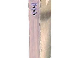
CPCI500DC 6064768 Murata Power Solutions Inc, CPCI500DC 6064768 Datasheet - Page 2

CPCI500DC 6064768
Manufacturer Part Number
CPCI500DC 6064768
Description
Linear & Switching Power Supplies 500W CPCI 5V 55A
Manufacturer
Murata Power Solutions Inc
Datasheet
1.CPCI500D-2C.pdf
(4 pages)
Specifications of CPCI500DC 6064768
Product
Switching
Output Power Rating
500 W
Number Of Outputs
2
Output Voltage (channel 2)
12 V
Dimensions
9.18 mm L x 6.68 mm W x 0.8 mm H
Lead Free Status / Rohs Status
Lead free / RoHS Compliant
GENERAL CHARACTERISTICS
Parameter
Efficiency
Switching Frequency
MTBF
Weight
PROTECTION
Parameter
Thermal Shutdown
Output Power Limit
Input Protection
Over-voltage Protection
Parameter
Output Overload Protection
Hot-Swap Capability
Output Fault Isolation
STATUS & CONTROL SIGNALS & INDICATORS
Name
Hot-Swap Enable
Output Inhibit
DC Good
Remote Sense
Fan Alarm
Power Present Indicator LED
DC Good Indicator LED
Fan Good Indicator LED
Sync Start
Power Supply Present
ENVIRONMENTAL CHARACTERISTICS
Parameter
AmbientOperatingTemperature
Ambient Storage Temperature
Humidity
Altitude
Cooling
www.murata-ps.com
Conditions/Response
Automatic recovery upon restoration to operational temperatures
Automatic recovery
Internal line fuse, Littlefuse BLN 25P ROHS or equivalent
Output V1, latching
Output V2, latching
Conditions/Response
Outputs are individually protected against overloads and indefinite short circuit with automatic recovery upon removal of the fault condition.
Design Verification Testing (DVT) confirms that voltage excursions on the output buses resulting from insertion/extraction events do not exceed the
specified maximum of 5%. However, routing of power and signal lines in the mating backplane is critical to minimization of such excursions. In
addition, performance can be critically affected by load characteristics including resistance, negative resistance, and reactive components. While
the control loop responses have been designed for optimum hot-swap performance over a wide range of characteristics, there may be instances
where the voltage excursions exceed published specifications. In such cases, the control loop responses can be modified to perform optimally.
Output isolation devices are present in all outputs to isolate faults within a failed power supply.
Description
Short pin on connector will enable the outputs when the mating pin is tied to DC GRD. Supply will not power up until this pin is engaged to its
mate in the backplane. Unit output will be inhibited as pin is disengaged from the mating connector.
Secondary referenced; active low, TTL compatible. Logic “0” or short circuit to Logic RTN (pin 40 or 43) inhibits all outputs.
Secondary referenced. Open collector signal with an internal 2.2k pull-up resistor is connected to the +5V output. TTL signal will transition high
when all outputs are between 90% and 110% of their nominal voltage.
Connection of the sense leads across the load at the desired point of regulation will compensate for voltage distribution drops up to 700mV
between the output terminals of the power supply and the point of connection. The unit reverts to local sensing if the sense lines are opened for
any reason. The output is protected against shorted or open leads. Applies to all outputs.
Secondary referenced; TTL compatible; active low. Signal transitions to a Logic 0 denotes a thermal warning.
A green LED will be illuminated when the input voltage is present and above the minimum requirement.
A green LED will be illuminated when the output voltages are within 90-110% of specification, coincident with assertion of the DC Good signal.
This LED will be extinguished if any of the output voltages is outside of this range.
A green LED will be illuminated when the fan is operational, coincident with de-assertion of the Fan Alarm signal. This LED will be extinguished in
the event of a fan failure.
A power supply generated signal used to simultaneously start power supplies connected in parallel when the load on any output exceeds a single
power supply’s capacity for that output. These pins must be bused together at the backplane in parallel/redundant applications (N+n) when N>1.
In simple redundant (1+1) or non-parallel applications (1+0), the pin can be ignored.
This pin presents a DC ground signal to the mating pin in the backplane. It is intended to be used by the system to detect the presence of a
power supply when the supply is mated into an available position.
Conditions
De-rate output power linearly above 40ºC to 250W at 60ºC.
Operating; non-condensing
Storage; non-condensing
Operating. De-rate ambient temperature by 2Cº per 1000ft above 5000ft.
Storage
Self-cooled by internal fan
Conditions
48Vdc input, 500W load (dependent upon load profile)
Calculated per MIL-HDBK-217F, 25ºC, ground benign
Unpackaged
500W 6Ux4HP DC/DC CompactPCI™ Power Supply
Technical enquiries email: sales@murata-ps.com, tel:
-200
-200
Min
-25
10
0
5
Min
6.0
3.9
cPCI500 Series
Min
84
TDC_cPCI500 Series.B01 Page 2 of 4
Typ
530
Typ
6.5
4.3
90
Inception
Typ
3.6
65
72
10000
40000
+125
Max
60
95
95
Max
7.0
4.7
Max
25
+1 508 339 3000
Units
Units
Units
khrs
kHz
Vdc
Vdc
kg
%
ºC
ºC
ºC
%
%
W
ft
ft
A


