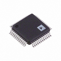
AD9954YSVZ Analog Devices Inc, AD9954YSVZ Datasheet - Page 29

AD9954YSVZ
Manufacturer Part Number
AD9954YSVZ
Description
IC DDS DAC 14BIT 1.8V 48-TQFP
Manufacturer
Analog Devices Inc
Datasheet
1.AD9954YSVZ-REEL7.pdf
(40 pages)
Specifications of AD9954YSVZ
Resolution (bits)
14 b
Master Fclk
400MHz
Tuning Word Width (bits)
32 b
Voltage - Supply
1.71 V ~ 1.96 V
Operating Temperature
-40°C ~ 105°C
Mounting Type
Surface Mount
Package / Case
48-TQFP Exposed Pad, 48-eTQFP, 48-HTQFP, 48-VQFP
Data Rate
25Mbps
Rf Ic Case Style
TQFP
No. Of Pins
48
Supply Voltage Range
1.71V To 1.89V, 3.135V To 3.465V
Operating Temperature Range
-40°C To +105°C
Msl
MSL 3 - 168 Hours
Termination Type
SMD
Rohs Compliant
Yes
Filter Terminals
SMD
Lead Free Status / RoHS Status
Lead free / RoHS Compliant
For Use With
AD9954/PCBZ - BOARD EVAL FOR 9954
Lead Free Status / RoHS Status
Lead free / RoHS Compliant, Lead free / RoHS Compliant
Available stocks
Company
Part Number
Manufacturer
Quantity
Price
Company:
Part Number:
AD9954YSVZ
Manufacturer:
ADI
Quantity:
210
Company:
Part Number:
AD9954YSVZ
Manufacturer:
Analog Devices Inc
Quantity:
10 000
Part Number:
AD9954YSVZ
Manufacturer:
ADI/亚德诺
Quantity:
20 000
Company:
Part Number:
AD9954YSVZ-REEL7
Manufacturer:
UBR
Quantity:
6 000
Company:
Part Number:
AD9954YSVZ-REEL7
Manufacturer:
Analog Devices Inc
Quantity:
10 000
CONTROL REGISTER BIT DESCRIPTIONS
Control Function Register No. 1 (CFR1)
The CFR1 is used to control the various functions, features,
and modes of the AD9954. The functionality of each bit follows.
CFR1<31>: RAM Enable Bit
CFR1<31> = 0 (default). The RAM is disabled for operation.
Either single-tone mode of operation or linear sweep mode of
operation is enabled.
CFR1<31> = 1. The RAM is enabled for operation. Access
control for normal operation is controlled via the mode control
bits of the RSCW for the current profile.
CFR1<30>: RAM Destination Bit
If CFR1<31> is cleared, CFR1<30> is ignored.
CFR1<30> = 0 (default). If CFR1<31> is set, the RAM output
drives the phase accumulator (provides the FTW).
CFR1<30> = 1. If CFR1<31> is set, the RAM output drives the
phase-offset adder (POW).
CFR1<29:27>: Internal Profile Control Bits
These bits cause the profile bits to be ignored when the RAM is
being used and puts the AD9954 into an automatic profile loop
sequence that allows the user to implement a frequency/phase
composite sweep that runs without external inputs. See the
Internal Profile Control section for more details.
CFR1<26>: Load Amplitude Ramp Rate Control Bit
CFR1<26> = 0 (default). The amplitude ramp rate timer is
loaded only upon timeout (timer == 1); it is not loaded due to
an I/O update input signal.
CFR1<26> = 1. The amplitude ramp rate timer is loaded upon
either timeout (timer == 1) or at the time of an I/O update
input signal.
CFR1<25>: Shaped On-Off Keying Enable Bit
CFR1<25> = 0 (default). Shaped on-off keying is bypassed.
CFR1<25> = 1. Shaped on-off keying is enabled. See also
CFR1<24>.
CFR1<24>: Autoshaped On-Off Keying Enable Bit
If CFR1<25> is cleared, CFR1<24> is ignored.
CFR1<24> = 0 (default). Manual shaped on-off keying
operation. See the Shaped On-Off Keying section for details.
CFR1<24> = 1. Autoshaped on-off keying operation. See the
Shaped On-Off Keying section for details.
CFR1<23>: Automatic Synchronization Enable Bit
CFR1<23> = 0 (default). The automatic synchronization feature
of multiple AD9954s is inactive.
CFR1<23> = 1. The automatic synchronization feature of
multiple AD9954s is active. See the Synchronizing Multiple
AD9954s section for details.
Rev. B | Page 29 of 40
CFR1<22>: Software Manual Synchronization of Multiple
AD9954s
CFR1<22> = 0 (default). The manual synchronization feature is
inactive.
CFR1<22> = 1. The software-controlled manual synchronization
feature is executed. The SYNC_CLK rising edge is advanced by
one SYNC_CLK cycle, and this bit is autocleared. To advance
the rising edge multiple times, this bit needs to be set once for
each advance.
CFR1<21>: Linear Frequency Sweep Enable
CFR1<21> = 0 (default). The linear frequency sweep capability
of the AD9954 is inactive.
CFR1<21> = 1. The linear frequency sweep capability of the
AD9954 is enabled. See the Linear Sweep Mode section for details.
CFR1<20:16>: Not Used, Leave Clear
CFR1<15>: Linear Sweep Ramp Rate Load Control Bit
CFR1<15> = 0 (default). The linear sweep ramp rate timer is
loaded only upon timeout (timer == 1); it is not loaded due to
an I/O update input signal.
CFR1<15> = 1. The linear sweep ramp rate timer is loaded
either upon timeout (timer == 1) or at the time of an I/O
update input signal.
CFR1<14>: Autoclear Frequency Accumulator Bit
CFR1<14> = 0 (default). The current state of the frequency
accumulator is not impacted by receipt of an I/O update signal.
CFR1<14> = 1. The frequency accumulator is automatically and
synchronously cleared for one cycle upon receipt of an I/O
UPDATE signal.
CFR1<13>: Autoclear Phase Accumulator Bit
CFR1<13> = 0 (default). The current state of the phase
accumulator is not impacted by receipt of an I/O update signal.
CFR1<13> = 1. The phase accumulator is automatically and
synchronously cleared for one cycle upon receipt of an I/O
update signal.
CFR1<12>: Sine/Cosine Select Bit
CFR1<12> = 0 (default). The angle-to-amplitude conversion
logic employs a cosine function.
CFR1<12> = 1. The angle-to-amplitude conversion logic
employs a sine function.
CFR1<11>: Clear Frequency Accumulator
CFR1<11> = 0 (default). The frequency accumulator functions
as normal.
CFR1<11> = 1. The frequency accumulator memory elements
are cleared and held clear until this bit is cleared.
AD9954


