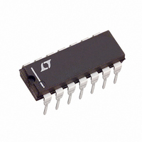
LT1791CN#PBF Linear Technology, LT1791CN#PBF Datasheet - Page 4

LT1791CN#PBF
Manufacturer Part Number
LT1791CN#PBF
Description
IC TXRX RS485/RS422 60V 14-DIP
Manufacturer
Linear Technology
Type
Transceiverr
Specifications of LT1791CN#PBF
Number Of Drivers/receivers
1/1
Protocol
RS422, RS485
Voltage - Supply
4.75 V ~ 5.25 V
Mounting Type
Through Hole
Package / Case
14-DIP (0.300", 7.62mm)
Device Type
Differential
Interface Type
RS422, RS485
No. Of Drivers
1
Supply Voltage Range
4.75V To 5.25V
Driver Case Style
DIP
No. Of Pins
14
Operating Temperature Range
0°C To +70°C
Rohs Compliant
Yes
Lead Free Status / RoHS Status
Lead free / RoHS Compliant
Available stocks
Company
Part Number
Manufacturer
Quantity
Price
DC ELECTRICAL CHARACTERISTICS
LT1785/LT1785A/
LT1791/LT1791A
temperature range, otherwise specifi cations are at T
SYMBOL PARAMETER
V
V
V
V
Δ|V
V
V
I
I
V
ΔV
V
V
R
I
I
4
IN1
IN2
SC
CC
TH
OD1
OD2
OD
OC
IH
IL
OH
OL
IN
TH
OC
|
Differential Driver Output Voltage (Unloaded)
Differential Driver Output Voltage (With Load)
Change in Magnitude of Driver Differential Output
Voltage for Complementary Output States
Driver Common Mode Output Voltage
Change in Magnitude of Driver Common Mode Output
Voltage for Complementary Output States
Input High Voltage
Input Low Voltage
Input Current
Input Current (A, B); (LT1791 or LT1785 with DE = 0V)
Differential Input Threshold Voltage for Receiver
Receiver Input Hysteresis
Receiver Output High Voltage
Receiver Output Low Voltage
Three-State (High Impedance) Output Current at
Receiver 0V < V
Receiver Input Resistance (LT1791)
LT1785
RS485 Unit Load
Driver Short-Circuit Current
Driver Output Fault Current
Receiver Short-Circuit Current
Driver Three-State Output Current
Supply Current
OUT
< 6V
A
= 25°C, V
CONDITIONS
I
R = 50Ω (RS422), Figure 1
R = 27Ω (RS485), Figure 1
R = 18Ω
R = 27Ω or R = 50Ω, Figure 1
R = 27Ω or R = 50Ω, Figure 1
R = 27Ω or R = 50Ω, Figure 1
DI, DE, RE
DI, DE, RE
DI, DE, RE
V
V
–60V ≤ V
LT1785/LT1791: –7V ≤ V
LT1785A/LT1791A: –7V ≤ V
–7V < V
I
I
RE > 2V or Power Off
–7V ≤ V
– 60V ≤ V
–7V ≤ V
V
V
V
V
0V ≤ V
–7V ≤ V
–60V ≤ V
No Load, RE = 0V, DE = 5V
No Load, RE = 5V, DE = 5V
No Load, RE = 0V, DE = 0V
No Load, RE = 5V, DE = 0V
O
O
O
IN
IN
OUT
OUT
O
O
= 0
= –400μA, V
= 1.6mA, V
CC
= 60V
= –60V
= 12V
= –7V
The
= HIGH, Force V
= LOW, Force V
= 5V.
O
CM
CM
CM
O
≤ V
IN
O
CM
≤ 12V
l
≤ 60V
< 12V
≤ 12V
≤ 12V
≤ 60V
CC
denotes the specifi cations which apply over the full operating
≤ 60V
ID
ID
= –200mV
= 200mV
O
O
= 12V
= –7V
CM
CM
≤ 12V
≤ 12V
l
l
l
l
l
l
l
l
l
l
l
l
l
l
l
l
l
l
l
l
l
l
l
l
l
l
l
l
l
l
l
–0.15
MIN
–0.2
–0.2
–0.2
2.0
1.5
1.2
3.5
–6
–1
85
50
35
35
–6
–6
2
2
–0.08
2.70
2.45
0.15
TYP
125
125
4.1
2.2
2.5
0.3
5.5
5.5
4.5
0.2
20
90
4
MAX
0.25
250
250
±35
0.2
0.2
0.8
0.3
0.2
0.5
0.3
0.3
5
3
5
6
0
1
6
6
9
9
8
178591fc
UNITS
mA
mA
mA
mV
mA
mA
mA
mA
mA
mA
mA
mA
mA
mA
mA
kΩ
kΩ
kΩ
μA
μA
V
V
V
V
V
V
V
V
V
V
V
V
V


