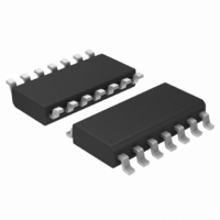
AMIS41682CANM1G ON Semiconductor, AMIS41682CANM1G Datasheet - Page 11

AMIS41682CANM1G
Manufacturer Part Number
AMIS41682CANM1G
Description
TRANSCEIVER CAN 3.3V DGTL 14SOIC
Manufacturer
ON Semiconductor
Type
Transceiverr
Datasheet
1.AMIS41683CANN1G.pdf
(16 pages)
Specifications of AMIS41682CANM1G
Number Of Drivers/receivers
1/1
Protocol
CAN
Voltage - Supply
4.75 V ~ 5.25 V
Mounting Type
Surface Mount
Package / Case
14-SOIC (3.9mm Width), 14-SOL
Operating Supply Voltage
5 V
Supply Current
8 mA
Operating Temperature Range
- 40 C to + 125 C
Mounting Style
SMD/SMT
Product
CAN
Lead Free Status / RoHS Status
Lead free / RoHS Compliant
Other names
766-1016
Available stocks
Company
Part Number
Manufacturer
Quantity
Price
Company:
Part Number:
AMIS41682CANM1G
Manufacturer:
ON Semiconductor
Quantity:
413
Table 9. TIMING CHARACTERISTICS AMIS−4168x
+150°C; unless otherwise specified.
t
t
t
t
t
t
t
t
D
t(r−d)
t(d−r)
PD(L)
PD(H)
CANH(min)
CANL(min)
det
rec
Symbol
pc
CANL and CANH Output
Transition Time for
Recessive−to−Dominant
CANL and CANH Output
Transition Time for
Dominant−to−Recessive
Propagation Delay TXD to
RXD (LOW)
Propagation Delay TXD to
RXD (HIGH)
Minimum Dominant Time for
Wake−up on Pin CANH
Minimum Dominant Time for
Wake−up on Pin CANL
Failure Detection Time
Failure Recovery Time
Pulse−Count Difference
Between CANH and CANL
Parameter
10 to 90%;
C1 = 10 nF; C2 = 0; R1 = 125 W (See Figure 6)
10 to 90%;
C1 = 1 nF; C2 = 0; R1 = 125 W (See Figure 6)
Failures 1, 2, 5, and 6a (See Figures 4 and 6)
Failures 3, 3a, 4, 6, and 7 (See Figures 4 and 6)
C1 = 1 nF; C2 = 0; R1 = 125 W C1 = C2 = 3.3 nF;
R1 = 125 W
C1 = 1 nF; C2 = 0; R1 = 125 W
C1 = C2 = 3.3nF; R1 = 125 W
Failures 1, 2, 5, and 6a (See Figures 4 and 6)
C1 = 1nF; C2 = 0; R1 = 125 W
C1 = C2 = 3.3nF; R1 = 125 W
Failures 3, 3a, 4, 6, and 7 (See Figures 4 and 6)
C1 = 1 nF; C2 = 0; R1 = 125 W
C1 = C2 = 3.3 nF; R1 = 125 W
No Failures
C1 = 1 nF; C2 = 0; R1 = 125 W
C1 = C2 = 3.3 nF; R1 = 125 W
No Failures
C1 = 1 nF; C2 = 0; R1 = 125 W
C1 = C2 = 3.3nF; R1 = 125 W
Low Power Modes; V
Low Power Modes; V
Normal Mode
Failure 3 and 3a
Failure 4, 6 and 7
Low Power Modes; V
Failure 3 and 3a
Failure 4 and 7
Normal Mode
Failure 3 and 3a
Failure 4 and 7
Failure 6
Low Power Modes; V
Failures 3, 3a, 4, and 7
Normal Mode and Failures 1, 2, 4, and 6a
Failure Detection (Pin ERR becomes LOW)
Failure Recovery (Pin ERR becomes HIGH)
http://onsemi.com
V
CC
= 4.75 V to 5.25 V, V
Conditions
11
BAT
BAT
BAT
BAT
= 12 V
= 12 V
= 12 V
= 12 V
BAT
= 5 V to 27 V, V
0.35
Min
125
0.2
1.6
0.3
1.6
0.1
0.3
0.3
7
7
7
STB
= V
0.60
0.75
0.75
Typ
0.3
1.4
1.2
1.4
1.2
1.5
2.5
1.2
2.5
1.2
1.5
CC
4
4
, T
J
= −40°C to
Max
750
1.4
0.7
1.5
2.1
1.9
2.1
1.9
2.2
1.5
3.0
1.9
3.0
1.9
2.2
8.0
1.6
8.0
1.6
1.6
1.6
38
38
38
Unit
ms
ms
ms
ms
ms
ms
ms
ms
ms
ms
ms
ms
ms
ms
ms
ms
−


