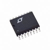
LTC489ISW#PBF Linear Technology, LTC489ISW#PBF Datasheet

LTC489ISW#PBF
Specifications of LTC489ISW#PBF
Available stocks
Related parts for LTC489ISW#PBF
LTC489ISW#PBF Summary of contents
Page 1
... The receiver has a fail-safe feature which guarantees a high output state when the inputs are left open. Both AC and DC specifi cations are guaranteed 4.75V to 5.25V supply voltage range. L, LT, LTC and LTM are registered trademarks of Linear Technology Corporation. All other trademarks are the property of their respective owners RECEIVER 120Ω ...
Page 2
LTC488/LTC489 ABSOLUTE MAXIMUM RATINGS (Note 1) Supply Voltage (V ) ................................................12V CC Control Input Currents .......................... –25mA to 25mA Control Input Voltages ..................–0. Receiver Input Voltages ..........................................±14V Receiver Output Voltages ..............–0. PIN CONFIGURATION LTC488 TOP VIEW ...
Page 3
... LTC489CN#TRPBF LTC489CSW#PBF LTC489CSW#TRPBF LTC489IN#PBF LTC489IN#TRPBF LTC489ISW#PBF LTC489ISW#TRPBF Consult LTC Marketing for parts specifi ed with wider operating temperature ranges. Consult LTC Marketing for information on non-standard lead based fi nish parts. For more information on lead free part marking, go to: For more information on tape and reel specifi cations, go to: DC ELECTRICAL CHARACTERISTICS temperature range, otherwise specifi ...
Page 4
LTC488/LTC489 TYPICAL PERFORMANCE CHARACTERISTICS Receiver Output Low Voltage vs Temperature 8mA 0.9 0.8 0.7 0.6 0.5 0.4 0.3 0.2 0.1 0 –50 – 100 TEMPERATURE (°C) 4889 G01 Receiver Output Low Voltage vs ...
Page 5
PIN FUNCTIONS B 1 (Pin 1): Receiver 1 Input. A1 (Pin 2): Receiver 1 Input. RO1 (Pin 3): Receiver 1 Output. If the receiver output is enabled, then if A > 200mV, RO1 will be high ...
Page 6
LTC488/LTC489 TEST CIRCUITS D Note: The input pulse is supplied by a generator having the following characteristics 1MHz, Duty Cycle = 50%, t Figure 2. Receiver Enable and Disable Timing Test Circuit SWITCHING TIME WAVEFORMS V OD2 INPUT ...
Page 7
APPLICATIONS INFORMATION Typical Application A typical connection of the LTC488/LTC489 is shown in Figure 5. Two twisted-pair wires connect driver/ receiver pairs for half-duplex data transmission. There are no restrictions on where the chips are connected to ...
Page 8
LTC488/LTC489 APPLICATIONS INFORMATION data rate. With lower quality PVC cables, the dielectric loss factor can be 1000 times worse. PVC twisted-pairs have terrible losses at high data rates (> 100kbps), and greatly reduce the maximum cable length. At low data ...
Page 9
APPLICATIONS INFORMATION Receiver Open-Circuit Fail-Safe Some data encoding schemes require that the output of the receiver maintains a known state (usually a logic 1) when the data is fi nished transmitting and all drivers on the line are forced in ...
Page 10
LTC488/LTC489 PACKAGE DESCRIPTION .300 – .325 (7.620 – 8.255) .008 – .015 (0.203 – 0.381) +.035 .325 –.015 ( ) +0.889 8.255 –0.381 NOTE: INCHES 1. DIMENSIONS ARE MILLIMETERS *THESE DIMENSIONS DO NOT INCLUDE MOLD FLASH OR PROTRUSIONS. MOLD FLASH ...
Page 11
... MOLD FLASH OR PROTRUSIONS SHALL NOT EXCEED .006" (0.15mm) Information furnished by Linear Technology Corporation is believed to be accurate and reliable. However, no responsibility is assumed for its use. Linear Technology Corporation makes no representa- tion that the interconnection of its circuits as described herein will not infringe on existing patent rights. ...
Page 12
... Full-Duplex in SO-8 1μA Shutdown Mode Lowest Power on 5V Supply Low EMI/Low Power with Shutdown 10Mbps Operation Up to 256 Nodes on a Bus 52Mbps, Pin Compatible with LTC485 52Mbps, Pin Compatible LTC490/LTC491 LT 0309 REV B • PRINTED IN USA © LINEAR TECHNOLOGY CORPORATION 1992 4889fb ...


