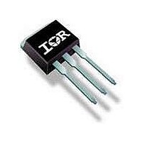
VS-32CTQ030-1PBF Vishay, VS-32CTQ030-1PBF Datasheet

VS-32CTQ030-1PBF
Specifications of VS-32CTQ030-1PBF
Related parts for VS-32CTQ030-1PBF
VS-32CTQ030-1PBF Summary of contents
Page 1
SCHOTTKY RECTIFIER Major Ratings and Characteristics Characteristics Values I Rectangular 40 F(AV) waveform V 45 RRM μs sine 1240 FSM Apk 125°C 0. (per leg) T range - ...
Page 2
Bulletin PD-20544 rev. D 07/06 Voltage Ratings Parameters V Max. DC Reverse Voltage ( Max. Working Peak Reverse Voltage (V) RWM Absolute Maximum Ratings Parameters I Max. Average Forward (Per Leg) F(AV) Current * See ...
Page 3
... Rectangular Pulse Duration (S ec onds) 1 Characteristics (Per Leg) thJC Bulletin PD-20544 rev. D 07/ 150°C J 125°C 100°C 75°C 50°C 25° evers e Voltage - V (V) R Vs. Reverse Voltage (Per Leg 25° everse Voltage - V (V) R Fig Typical Junction Capacitance Vs. Reverse Voltage (Per Leg thJC DM 10 100 3 ...
Page 4
... Average Forward Current - I Fig Max. Allowable Case Temperature Vs. Average Forward Current (Per Leg) 10000 1000 100 10 S quare Wave Pulse Duration - t Fig Max. Non-Repetitive Surge Current (Per Leg) DUT CURRENT MONIT OR Fig Unclamped Inductive Test Circuit ...
Page 5
Outline Table Conform to JEDEC outline TO-220AB Conform to JEDEC outline D www.irf.com 40CTQ045, 40CTQ045S, 40CTQ045-1 2 Pak (SMD-220) Dimensions in millimeters and (inches) Bulletin PD-20544 rev. D 07/06 5 ...
Page 6
Bulletin PD-20544 rev. D 07/06 Outline Table Tape & Reel Information 6 Modified JEDEC outline TO-262 Dimensions in millimeters and (inches) Dimensions in millimeters and (inches) www.irf.com ...
Page 7
Part Marking Information TO-220 EXAMPLE: THIS IS A 40CTQ045 LOT CODE 1789 ASSEMBLED ON WW 19, 2000 IN THE ASSEMBLY LINE "C" PAK THIS IS A 40CTQ045S LOT CODE 8024 ASSEMBLED ON WW 02, 2003 IN ASSEMBLY LINE ...
Page 8
Bulletin PD-20544 rev. D 07/06 Ordering Information Table Device Code WORLD HEADQUARTERS: 233 Kansas St., El Segundo, California 90245, ...


