VS-MBR2545CT-1PBF Vishay, VS-MBR2545CT-1PBF Datasheet
VS-MBR2545CT-1PBF
Specifications of VS-MBR2545CT-1PBF


Related parts for VS-MBR2545CT-1PBF

VS-MBR2545CT-1PBF Summary of contents
Page 1
SCHOTTKY RECTIFIER Major Ratings and Characteristics Characteristics Values I Rectangular waveform 30 F(AV) (Per Device 130°C 30 FRM C (Per Leg) V 35/45 RRM µs sine 1060 FSM ...
Page 2
MBR2545CT, MBRB2545CT, MBR2545CT-1 Bulletin PD-2.322 rev. C 01/03 Voltage Ratings Parameters V Max. DC Reverse Voltage ( Max. Working Peak Reverse Voltage (V) RWM Absolute Maximum Ratings Parameters I Max. Average Forward (Per Leg) F(AV) Current (Per Device) ...
Page 3
... Rectangular Pulse Duration (Seconds) 1 Characteristics (Per Leg) thJC Bulletin PD-2.322 rev. C 01/ 150°C J 125°C 100°C 75°C 50°C 25° Reverse Voltage - V (V) R Vs. Reverse Voltage (Per Leg 25° Reverse Voltage - V (V) R Fig Typical Junction Capacitance Vs. Reverse Voltage (Per Leg thJC ...
Page 4
... Square wave (D = 0.50) 120 Rated V applied R 110 see note (2) 100 Average Forward Current - I Fig Max. Allowable Case Temperature Vs. Average Forward Current (Per Leg) 1000 100 10 Square Wave Pulse Duration - t Fig Max. Non-Repetitive Surge Current (Per Leg) (2) Formula used ( REV Pd = Forward Power Loss = I ...
Page 5
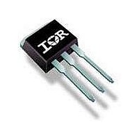
Ordering Information Table Device Code Outline Table 10.54 (0.41) MAX. 15.24 (0.60) 14.84 (0.58 14.09 (0.55) 13.47 (0.53) 1.40 (0.05) 1.15 (0.04 4.57 (0.18) 4.32 (0.17) www.irf.com MBR2545CT, ...
Page 6
MBR2545CT, MBRB2545CT, MBR2545CT-1 Bulletin PD-2.322 rev. C 01/03 Outline Table 93° 15.49 (0.61) 14.73 (0.58) 1.40 (0.055) 3X 1.14 (0.045) BASE COMMON CATHODE ANODE COMMON ANODE CATHODE 1 2 Conform to JEDEC outline D Dimensions are ...
Page 7
Outline Table Modified JEDEC outline TO-262 Dimensions in millimeters and (inches) IR WORLD HEADQUARTERS: 233 Kansas St., El Segundo, California 90245, USA Tel: (310) 252-7105 www.irf.com MBR2545CT, MBRB2545CT, MBR2545CT-1 Bulletin PD-2.322 rev. C 01/03 1 ANODE 1 Data and specifications ...
Page 8
This datasheet has been download from: www.datasheetcatalog.com Datasheets for electronics components. ...