MAL214097111E3 Vishay, MAL214097111E3 Datasheet
MAL214097111E3
Specifications of MAL214097111E3


Related parts for MAL214097111E3

MAL214097111E3 Summary of contents
Page 1
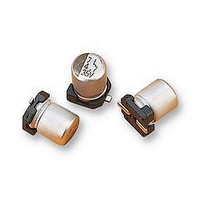
... CRH Vishay BCcomponents SMD (Chip), High Temperature Fig.1 Component outline 140 CRH 175 TMP 125 °C 175 °C solid SMD Lower temp. 150 CRZ QUICK REFERENCE DATA DESCRIPTION Nominal case sizes ( mm) Rated capacitance range Tolerance Rated voltage range Category temperature range Endurance test at 125 ° ...
Page 2
... H MAX. MAX. 0 MAX MAX. MAX. Fig.2 Dimensional outline For technical questions, contact: aluminumcaps1@vishay.com 140 CRH Vishay BCcomponents 35 50 → → → → → → → 12 12 12 12 12 12 12 ...
Page 3
... CRH Vishay BCcomponents Table 1 DIMENSIONS in millimeters AND MASS NOMINAL CASE CASE SIZE CODE 0810 1010 1014 12 1213 12 1216 1616 1621 1816 1821 Table 2 TAPE AND REEL DIMENSIONS in millimeters, PACKAGING QUANTITIES NOMINAL CASE CASE SIZE CODE 0810 ...
Page 4
... Fig.3 Recommended soldering pad dimensions b c 2.5 3.0 2.5 4.0 2.5 4.0 2.5 4.0 2.5 4.0 9.6 4.7 9.6 4.7 9.6 4.7 9.6 4.7 For technical questions, contact: aluminumcaps1@vishay.com 140 CRH Vishay BCcomponents ensure good soldering Case size Ø D ≥ 4.2 5.0 4.2 5 ...
Page 5
... CRH Vishay BCcomponents STANDARD SOLDERING PROFILE FOR LEAD (Pb)-FREE REFLOW PROCESS T (°C) T Peak 230 217 200 150 Table 4 REFLOW SOLDERING CONDITIONS for MAL214097xxxE3 PROFILE FEATURES Max. time from 25 ° Peak Min. ramp-up rate to 150 °C Max. time from 150 °C to 200 °C, (t ...
Page 6
... Fig.5 Maximum temperature load during reflow soldering CASE CODE 1010 300 s 3 K/s 150 s 110 s 0 260 ° K K/s For technical questions, contact: aluminumcaps1@vishay.com 140 CRH Vishay BCcomponents time (s) CASE CODE CASE CODE 1213 to 1216 1616 to 1821 300 s 300 s 3 K/s 3 K/s 150 s 150 s ...
Page 7
... CRH Vishay BCcomponents ELECTRICAL DATA SYMBOL DESCRIPTION C rated capacitance at 100 Hz, tolerance ± rated RMS ripple current at 100 kHz, 125 ° max. leakage current after 2 minutes tan δ max. dissipation factor at 100 Hz Z max. impedance at 100 kHz Note • Unless otherwise specified, all electrical values in Table 6 apply ° ...
Page 8
... For technical questions, contact: aluminumcaps1@vishay.com 140 CRH Vishay BCcomponents Z ORDERING ORDERING 100 kHz (1) CODE CODE 20 °C MAL2140... MAL2140... (Ω) 0.40 97003E3 0.25 97001E3 99001E3 0.20 97002E3 ...
Page 9
... CRH Vishay BCcomponents Table 7 ADDITIONAL ELECTRICAL DATA PARAMETER Voltage Surge voltage for short periods Reverse voltage for short periods Current Leakage current Inductance Equivalent series inductance (ESL) Resistance Equivalent series resistance (ESR) at 100 Hz CAPACITANCE (C) 1 1.1 1.0 2 0 capacitance at 20 °C, 100 Hz 0 Fig ...
Page 10
... Fig.10 Typical impedance as a function of frequency ENDURANCE AT 125 °C (h) 1000 1000 1000 2000 2000 3000 3000 3000 3000 For technical questions, contact: aluminumcaps1@vishay.com 140 CRH Vishay BCcomponents Curve 1: 22-63-0810 Curve 2: 47-63-1010 Curve 3: 68-63-1014 Curve 4: 100-63-1213 Curve 5: 220-63-1216 Curve 6: 330-63-1616 Curve 7: 680-63-1821 ...
Page 11
... CRH Vishay BCcomponents RIPPLE CURRENT AND USEFUL LIFE I = actual ripple current at 100 kHz rated ripple current at 100 kHz, 125 °C R (1) Useful life at 125 °C and I applied: see table 8 R Fig.11 Multiplier of useful life as a function of ambient temperature and ripple current load ...
Page 12
... applied for 30 min before measurement T = 125 °C: amb 125 0.5 V, followed by 125 For technical questions, contact: aluminumcaps1@vishay.com 140 CRH Vishay BCcomponents REQUIREMENTS ΔC/C: ± tan δ ≤ spec. limit ≤ spec. limit 6.3 V; ΔC/C: ± ≥ ΔC/C: ± tan δ ≤ spec. limit ≤ ...
Page 13
... Vishay disclaims any and all liability arising out of the use or application of any product described herein or of any information provided herein to the maximum extent permitted by law. The product specifications do not expand or otherwise modify Vishay’ ...