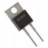
TBH25P30R0JE Ohmite, TBH25P30R0JE Datasheet

TBH25P30R0JE
Manufacturer Part Number
TBH25P30R0JE
Description
RESISTOR THICK FILM, 30OHM, 25W, 5%
Manufacturer
Ohmite
Datasheet
1.TDH35P20R0JE-TR.pdf
(1 pages)
Specifications of TBH25P30R0JE
Resistance
30ohm
Resistance Tolerance
± 5%
Power Rating
25W
Voltage Rating
350V
Temperature Coefficient
± 50ppm/°C
Resistor Element Material
Thick Film
Resistor Case Style
TO-220
Rohs Compliant
Yes
TBH Series
25 Watt TO220 Package
Thick Film Power
56
Note: These dimensions apply to TBH products manufactured after March 2007
ø0.151"
(3.84mm)
(1.32mm)
(0.81mm)
0.052"
0.032"
S t a n d a r d p a r t n u m b e r S f o r t b H S e r i e S
Ohmite Mfg. Co.
Ohms
10
15
22
30
33
47
51
75
0.030
0.036
0.040
0.047
0.050
0.075
2
7.5
(10.2mm ±0.2)
0.402" ±0.008
T B H 2 5 P 2 R 0 0 J E
(5.08mm)
Check product availability at
Series
0.200"
TBH25PR030JE
TBH25PR036JE
TBH25PR040JE
TBH25PR047JE
TBH25PR050JE
TBH25PR075JE
TBH25P2R00JE
TBH25P7R50JE
TBH25P10R0JE
TBH25P15R0JE
TBH25P22R0JE
TBH25P30R0JE
TBH25P33R0JE
TBH25P47R0JE
TBH25P51R0JE
TBH25P75R0JE
5% Tolerance
Part Number
o r d e r i n G i n f o r m a t i o n
1600 Golf Rd., Rolling Meadows, IL 60008 • 1-866-9-OHMITE • Int’l 1-847-258-0300 • Fax 1-847-574-7522 • www.ohmite.com • info@ohmite.com
0.110" ±0.012
(2.8mm ±0.3)
0.367"
(9.32mm)
0.108"
(0.274mm)
Ohm Value
Example:
R030 = 0.030 Ω
10R0 = 10 Ω
1K50 = 1500 Ω
RoHS compliant
Non-RoHS version unavailable
www.ohmite.com
Molding
0.487"
(12.37mm)
10,000
(3.48mm)
1000
1500
2000
2700
100
150
220
240
330
470
510
0.137"
Ohms
Tolerance
J = 5%, standard
(1.27mm)
0.050"
TBH25P100RJE
TBH25P150RJE
TBH25P220RJE
TBH25P240RJE
TBH25P330RJE
TBH25P470RJE
TBH25P510RJE
TBH25P1K00JE
TBH25P1K50JE
TBH25P2K00JE
TBH25P2K70JE
TBH25P10K0JE
5% Tolerance
Part Number
0.015"
(0.38mm)
0.255"
(6.48mm)
0.104" ±0.008
(2.65mm ±0.2)
(16.00mm)
0.630"
Ohmite’s TBH25 TO220 style
resistors are designed for a
variety of uses that require
intermediate heatsinkable
power at an economical price.
Engineered for industrial
applications, these resistors
deliver reliable performance to
traditional high-quality Ohmite
standards.
F e a T u r e s
• 25 Watts, @ 25°C case tempera-
• Non-Inductive Performance
• Low Thermal Resistance
• Anti-static tube packaging avail-
• Economically priced
• Resistance element is electrically
a P P L I C a T I O N s
• Power Supplies
• Industrial Controls
• Automotive Steering
• Pre-load/Damping
• Snubber/Bleeder
• Current Sensing
Load Life
Moisture Resistance (MIL-STD-202, method 106)
Short Time Overload (2x rated power, not to exceed
Solderability
Thermal Shock
Terminal Strength
Vibration
ture
able
insulated from metal heat sink
mounting tab
(1000hrs @ rated power)
1.5x max. operating voltage)
(MIL-STD-202, method 208)
(MIL-STD-202, method 107, cond. F)
(MIL-STD-202, method 211,
cond. A (pull test) 2.4N)
(MIL-STD-202, method 204, cond. D)
t e S t d a t a
s P e C I F I C a T I O N s
Material
Resistor: Thick film element
Case: High Temperature Plastic
Terminals: Solder coated phos-
Electrical:
Derating: 100% @ 25°C to 0% @
Dielectric Strength: 1000 VDC
Max. Mounting Torque: 0.9Nm
Operating Temperature Range:
Temperature Coefficient:
Thermal Resistance: 5°C/W
Tolerance: 5%
Power: 25 Watts. Rating based
Resistance Range: 0.03Ω -
Max. Operating Voltage: 350V
above 1Ω, Ni-Cu metal element
below 1Ω
pher bronze
150°C curve referenced to case
temperature
-55°C to +150°C
0.03-10Ω @ ±100ppm
11Ω-10KΩ @ ±50ppm
on 25°C case temperature. The
case temperature is to be used
for the purposes of establishing
the applied power limit. The case
temperature must be made with
thermocouple contacting the cen-
ter of the component’s mounting
tab mounted on designated heat
sink.
10KΩ. Standard values listed at
left, others available upon special
request.
max. ∆R ±1%
max. ∆R ±0.5%
max. ∆R ±0.3%
max. ∆R ±0.3%
max. ∆R ±0.2%
max. ∆R ±0.2%


