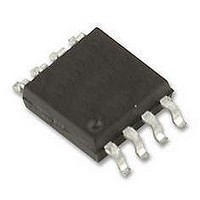
LTC6102IMS#PBF Linear Technology, LTC6102IMS#PBF Datasheet - Page 6

LTC6102IMS#PBF
Manufacturer Part Number
LTC6102IMS#PBF
Description
AMP, CURRENT SENSE, PRECISION, SMD
Manufacturer
Linear Technology
Datasheet
1.LTC6102CDDPBF.pdf
(26 pages)
Specifications of LTC6102IMS#PBF
No. Of Amplifiers
1
Input Bias Current
3nA
Output Current Per Channel
1mA
Input Offset Voltage
5µV
Bandwidth
200kHz
Supply Voltage Range
4V To 60V
Supply Current
650µA
Rohs Compliant
Yes
Available stocks
Company
Part Number
Manufacturer
Quantity
Price
LTC6102
LTC6102-1/LTC6102HV
ELECTRICAL CHARACTERISTICS
SYMBOL
I
f
Note 1: Stresses beyond those listed under Absolute Maximum Ratings
may cause permanent damage to the device. Exposure to any Absolute
Maximum Rating condition for extended periods may affect device
reliability and lifetime. In addition to the Absolute Maximum Ratings, the
output current of the LTC6102 must be limited to ensure that the power
dissipation in the LTC6102 does not allow the die temperature to exceed
150°C. See the Applications Information “Output Current Limitations Due
to Power Dissipation” for further information.
Note 2: The LTC6102C/LTC6102C-1/LTC6102HVC are guaranteed to meet
specifi ed performance from 0°C to 70°C. The LTC6102C/LTC6102C-1/
LTC6102HVC are designed, characterized and expected to meet specifi ed
performance from –40°C to 85°C but are not tested or QA sampled at
these temperatures. LTC6102I/LTC6102I-1/LTC6102HVI are guaranteed
operating temperature range, otherwise specifi cations are at T
V
6
S
S
+
= 12V, V
–
PARAMETER
Supply Current
Sampling Frequency
= 0V unless otherwise noted.
CONDITIONS
V
V
V
V
LTC6102HVC, LTC6102HVI
LTC6102HVH
+
+
+
+
= 5V, I
= 6V, I
= 12V, I
= 100V, I
OUT
OUT
OUT
OUT
= 0, R
= 0, R
= 0, R
= 0, R
(LTC6102HV) The
IN
IN
IN
A
= 10k, R
= 10k, R
IN
= 10k, R
= 25°C. R
= 10k, R
to meet specifi ed performance from –40°C to 85°C. The LTC6102H/
LTC6102H-1/LTC6102HVH are guaranteed to meet specifi ed performance
from –40°C to 125°C.
Note 3: These Parameters are guaranteed by design and are not 100%
tested. Thermocouple effects preclude measurements of these voltage
levels during automated testing.
Note 4: Limits are fully tested. Limit is determined by high speed
automated test capability.
Note 5: I
Please refer to the Typical Performance Characteristics section for
more information regarding actual typical performance. For tighter
specifi cations, please contact LTC Marketing.
OUT
OUT
OUT
OUT
= 100k
= 100k
IN
= 100k
= 100k
= 10Ω, R
l
B
specifi cation is limited by practical automated test resolution.
denotes the specifi cations which apply over the full
OUT
= 10k, V
l
l
l
l
l
SENSE
MIN
+
= V
+
(see Figure 1 for details),
TYP
275
280
290
420
10
MAX
400
475
425
500
450
525
575
650
675
UNITS
6102fd
kHz
μA
μA
μA
μA
μA
μA
μA
μA
μA


