VJ0603Y103KXAPW1BC Vishay, VJ0603Y103KXAPW1BC Datasheet
VJ0603Y103KXAPW1BC
Manufacturer Part Number
VJ0603Y103KXAPW1BC
Description
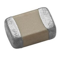
Multilayer Ceramic Capacitors (MLCC) - SMD/SMT 0603 0.01uF 50volts X7R 10%
Manufacturer
Vishay
Series
VJ0603r
Datasheet
1.VJ0603Y103KXAPW1BC.pdf
(14 pages)
Specifications of VJ0603Y103KXAPW1BC
Capacitance
0.01 uF
Tolerance
10 %
Voltage Rating
50 Volts
Operating Temperature Range
- 55 C to + 125 C
Temperature Coefficient / Code
X7R
Package / Case
0603 (1608 metric)
Product
General Type MLCCs
Dimensions
0.800 mm W x 1.600 mm L x 0.870 mm H
Dissipation Factor Df
2.5
Termination Style
SMD/SMT
Lead Free Status / Rohs Status
Details
Available stocks
Company
Part Number
Manufacturer
Quantity
Price
Company:

Part Number:
VJ0603Y103KXAPW1BC
Manufacturer:
Vishay
Quantity:
5 000


ELECTRICAL SPECIFICATIONS
Operating Temperature:
C0G (NP0): - 55 °C to + 125 °C
X5R: - 55 °C to + 85 °C
X7R: - 55 °C to + 125 °C
Y5V: - 25 °C to + 85 °C
Capacitance Range:
C0G (NP0): 0.5 pF to 39 nF
X5R: 47 nF to 22 μF
X7R: 100 pF to 10 μF
Y5V: 10 nF to 100 μF
Voltage Range:
C0G (NP0): 10 V
X5R: 6.3 V
X7R: 10 V
Y5V: 6.3 V
Temperature Coefficient of Capacitance (TCC):
C0G (NP0): 0 ppm/°C ± 30 ppm/°C from - 55 °C to + 125 °C
X5R: ± 15 % from - 55 °C to + 85 °C without voltage applied
X7R: ± 15 % from - 55 °C to + 125 °C without voltage applied
Y5V: + 30 %/- 80 % from - 25 °C to + 85 °C without voltage
Test Conditions for Capacitance Tolerance:
Preconditioning for X5R, X7R, Y5V MLCC: Perform a heat
treatment at + 150 °C ± 10 °C for 1 h, then leave in ambient
condition for 24 h ± 2 h before measurement
Revision: 30-Mar-12
applied
THIS DOCUMENT IS SUBJECT TO CHANGE WITHOUT NOTICE. THE PRODUCTS DESCRIBED HEREIN AND THIS DOCUMENT
DC
DC
DC
to 100 V
to 100 V
to 25 V
Surface Mount Multilayer Ceramic Chip Capacitors
www.vishay.com
DC
to 100 V
DC
DC
DC
ARE SUBJECT TO SPECIFIC DISCLAIMERS, SET FORTH AT
DC
for Commodity Applications
For technical questions, contact:
VJ....W1BC Basic Commodity Series
1
FEATURES
• Available from 0402 to 1210 body sizes
• Ultra stable C0G (NP0) dielectric
• High capacitance in X5R, X7R, Y5V
• For high frequency applications
• Ni-barrier with 100 % tin terminations
• Dry sheet technology process
• Noble Metal Electrode system (NME):
• Base Metal Electrode system (BME):
• Material categorization: For definitions of compliance
APPLICATIONS
• Consumer electronics
• Telecommunications
• Data processing
• Mobile applications
Test Conditions for Capacitance and DF Measurement:
Measured at conditions of 30 % to 70 % related humidity.
C0G (NP0): Apply 1.0 V
X5R/X7R: Caps 10 μF apply 1.0 V
Y5V:
Aging Rate:
C0G (NP0): 0 % per decade
X5R: 6.3 V
X7R: 10 V
Y5V: 6.3 V
Insulation Resistance (IR) at U
10 G or R x C 500 x F whichever is less
Dielectric Strength Test:
This is the maximum voltage the capacitors are tested 1 s to
5 s period and the charge/discharge current does not
exceed 50 mA.
100 V
For certain C0G (NP0) values
For X5R, X7R, Y5V and certain C0G (NP0) values
please see
mlcc@vishay.com
16 V
16 V
10 V
25 V
DC
DC
DC
: 250 % of rated voltage
DC
DC
1.0 kHz ± 10 %, at + 25 °C ambient temperature
Caps > 10 μF apply 0.5 V
120 Hz ± 20 %, at + 25 °C ambient temperature
Caps 10 μF apply 1.0 V
1.0 kHz ± 10 %, at + 20 °C ambient temperature
Caps > 10 μF apply 0.5 V
120 Hz ± 20 %, at + 20 °C ambient temperature
www.vishay.com/doc?91000
caps 1000 pF, at + 25 °C ambient temperature
Apply 1.0 V
caps > 1000 pF, at + 25 °C ambient temperature
DC
DC
DC
/25 V
/16 V
: 12.5 % maximum per decade
/10 V
www.vishay.com/doc?99912
: 1.5 % maximum per decade
: 1 % maximum per decade
: 7 % maximum per decade
DC
DC
DC
: 2 % maximum per decade
: 9 % maximum per decade
: 3 % maximum per decade
RMS
RMS
± 0.2 V
± 0.2 V
R
:
RMS
RMS
Document Number: 28548
, 1.0 MHz ± 10 % for
, 1.0 kHz ± 10 % for
RMS
RMS
RMS
RMS
± 0.2 V
± 0.2 V
± 0.2 V
± 0.2 V
Vishay
RMS
RMS
RMS
RMS
,
,
,
,
Related parts for VJ0603Y103KXAPW1BC
Image
Part Number
Description
Manufacturer
Datasheet
Request
R

Part Number:
Description:
357-036-542-201 CARDEDGE 36POS DL .156 BLK LOPRO
Manufacturer:
Vishay
Datasheet:
Part Number:
Description:
357-036-542-201 CARDEDGE 36POS DL .156 BLK LOPRO
Manufacturer:
Vishay
Datasheet:
Part Number:
Description:
357-036-542-201 CARDEDGE 36POS DL .156 BLK LOPRO
Manufacturer:
Vishay
Datasheet:
Part Number:
Description:
357-036-542-201 CARDEDGE 36POS DL .156 BLK LOPRO
Manufacturer:
Vishay
Datasheet:
Part Number:
Description:
357-036-542-201 CARDEDGE 36POS DL .156 BLK LOPRO
Manufacturer:
Vishay
Datasheet:
Part Number:
Description:
357-036-542-201 CARDEDGE 36POS DL .156 BLK LOPRO
Manufacturer:
Vishay
Datasheet:
Part Number:
Description:
357-036-542-201 CARDEDGE 36POS DL .156 BLK LOPRO
Manufacturer:
Vishay
Datasheet:
Part Number:
Description:
357-036-542-201 CARDEDGE 36POS DL .156 BLK LOPRO
Manufacturer:
Vishay
Datasheet:
Part Number:
Description:
357-036-542-201 CARDEDGE 36POS DL .156 BLK LOPRO
Manufacturer:
Vishay
Datasheet:
Part Number:
Description:
357-036-542-201 CARDEDGE 36POS DL .156 BLK LOPRO
Manufacturer:
Vishay
Datasheet:
Part Number:
Description:
357-036-542-201 CARDEDGE 36POS DL .156 BLK LOPRO
Manufacturer:
Vishay
Datasheet:
Part Number:
Description:
357-036-542-201 CARDEDGE 36POS DL .156 BLK LOPRO
Manufacturer:
Vishay
Datasheet:
Part Number:
Description:
357-036-542-201 CARDEDGE 36POS DL .156 BLK LOPRO
Manufacturer:
Vishay
Datasheet:
Part Number:
Description:
357-036-542-201 CARDEDGE 36POS DL .156 BLK LOPRO
Manufacturer:
Vishay
Datasheet:
Part Number:
Description:
357-036-542-201 CARDEDGE 36POS DL .156 BLK LOPRO
Manufacturer:
Vishay
Datasheet: