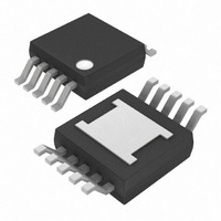
MAX7430EUB+T Maxim Integrated Products, MAX7430EUB+T Datasheet - Page 11

MAX7430EUB+T
Manufacturer Part Number
MAX7430EUB+T
Description
IC FILTER VIDEO SD 10-UMAX
Manufacturer
Maxim Integrated Products
Datasheet
1.MAX7432EUDT.pdf
(21 pages)
Specifications of MAX7430EUB+T
Filter Type
Low Pass
Frequency - Cutoff Or Center
5MHz
Number Of Filters
2
Max-order
6th
Voltage - Supply
4.5 V ~ 5.5 V
Mounting Type
Surface Mount
Package / Case
10-MSOP Exposed Pad, 10-HMSOP, 10-eMSOP
Lead Free Status / RoHS Status
Lead free / RoHS Compliant
The MSPB interface uses three pulses of different
widths to represent commands and data bits. Figure 4
shows the set of pulses that the single pin interface
uses to communicate with the device. A combination of
the one pulse (t
and prompt pulse (t
sends broadcast data to the devices on the bus.
Note: The zero pulse and prompt pulse are the same.
Initialization pulses are significantly longer and are
used only on power-up or software reset.
Table 5. MAX7432A Control Register
Figure 4. MSPB Interface Pulses
NAME
DEFAULT
NAME
DEFAULT
NAME
DEFAULT
TRANSACTION
ZERO/PROMPT
ONE PULSE
PULSE
PULSE
Standard Definition Video Reconstruction
Maxim’s Single Pin Bus (MSPB)
1
Applications Information
), zero pulse (t
(MSB)
—
—
—
______________________________________________________________________________________
0
0
0
t
P
0
), writes to, reads back from, and
t
1
t
T
t
P
ABSEL3
ABSEL2
ABSEL1
= t
0
= 5μs
1
1
1
0
t
1
), transaction pulse (t
= 30μs
Serial Interface
BYPASS3
BYPASS2
BYPASS1
t
T
1
1
1
= 100μs
CLEVEL3
CLEVEL2
CLEVEL1
T
),
0
0
0
Initialization is performed only after power-up or software
reset. It assigns a unique address to each device on the
bus. The time constant of the capacitor connected to
R
order in which the devices are initialized (address
assigned). The device with the largest time constant is
initialized first and so on, in descending order. Table 7
shows the “Initialize Wait” and “Initialize Time” pulse
widths needed for a specific capacitor value and toler-
ance. Program each device on the bus with this com-
mand sequence starting with the device with the biggest
capacitor. To reinitialize a device, cycle the power or use
a software reset. The following is the command
sequence and timing diagram (Figure 5) for initialization
as shown below. Chip ID is entered LSB first.
Note: If there is only one device on the bus, no initial-
ization is needed. Communicate to the device using the
broadcast command described on page 13.
Table 6. Boost Level Programming
EXT
BOOST1(3)
BOOST1(2)
BOOST1(1)
BOOST1_
in parallel with the 300kΩ resistor determines the
0
0
1
1
0
0
0
Filters and Buffers
MAX7428/MAX7430/MAX7432A
BOOST0(3)
BOOST0(2)
BOOST0(1)
BOOST0_
0
0
0
0
1
0
1
DISABLE3
DISABLE2
DISABLE1
OUT
OUT
OUT
FREQUENCY BOOST
0
0
0
RELATIVE HIGH
Initializing the
0.3dB to 0.5dB
0.6dB to 1.0dB
0.9dB to 1.5dB
0
FIRST BIT
—
—
—
0
0
0
(LSB)
11


