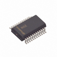
MAX7324AEG+ Maxim Integrated Products, MAX7324AEG+ Datasheet

MAX7324AEG+
Specifications of MAX7324AEG+
Related parts for MAX7324AEG+
MAX7324AEG+ Summary of contents
Page 1
... Detection Between Read Operations ♦ INT Output Alerts Change on Any Selection of Inputs ♦ AD0 and AD2 Inputs Select from 16 Slave Addresses ♦ Low 0.6µA Standby Current ♦ -40°C to +125°C Temperature Range PART MAX7324AEG+ MAX7324ATG+ +Denotes lead-free package. Applications *EP = Exposed paddle. PART MAX7324 13 ...
Page 2
I C Port Expander with Eight Push-Pull Outputs and Eight Inputs ABSOLUTE MAXIMUM RATINGS (All voltages referenced to GND.) Supply Voltage V+....................................................-0.3V to +6V SCL, SDA, AD0, AD2, RST, INT, I0–I7......................-0.3V to +6V O8–O15………….…………………………..…-0.3V to (V+ + 0.3V) O8–O15 ...
Page 3
I C Port Expander with Eight Push-Pull Outputs PORT AND INTERRUPT INT TIMING CHARACTERISTICS (V+ = +1.71V to +5.5V -40°C to +125°C, unless otherwise noted. Typical values are +3.3V PARAMETER SYMBOL Port-Output ...
Page 4
I C Port Expander with Eight Push-Pull Outputs and Eight Inputs (T = +25°C, unless otherwise noted.) A STANDBY CURRENT vs. TEMPERATURE 2.0 1.8 1.6 1.4 1.2 1 +3. +2.5V 0.8 0.6 0 ...
Page 5
I C Port Expander with Eight Push-Pull Outputs Detailed Description MAX7324–MAX7327 Family Comparison The MAX7324–MAX7327 family consists of four pin- compatible, 16-port expanders that integrate the func- tion of the MAX7320 and one of either the MAX7319, MAX7321, MAX7322, ...
Page 6
I C Port Expander with Eight Push-Pull Outputs and Eight Inputs Table 1. MAX7319–MAX7329 Family Comparison (continued INPUT PART SLAVE INPUTS INTERRUPT ADDRESS MASK MAX7326 4 101xxxx and 110xxxx MAX7327 8-PORT EXPANDERS MAX7319 ...
Page 7
I C Port Expander with Eight Push-Pull Outputs Table 1. MAX7319–MAX7329 Family Comparison (continued PART SLAVE INPUTS INTERRUPT ADDRESS MAX7323 110xxxx MAX7328 0100xxx MAX7329 0111xxx A latching interrupt output, INT, ...
Page 8
I C Port Expander with Eight Push-Pull Outputs and Eight Inputs Table 2. MAX7324 Address Map for Inputs I0–I7 PIN CONNECTION DEVICE ADDRESS AD2 AD0 SCL GND SCL SCL ...
Page 9
I C Port Expander with Eight Push-Pull Outputs Table 3. MAX7324 Address Map for Outputs O8–O15 PIN CONNECTION DEVICE ADDRESS AD2 AD0 SCL GND SCL SCL SCL 1 0 ...
Page 10
I C Port Expander with Eight Push-Pull Outputs and Eight Inputs The MAX7324 operates as a slave that sends and 2 receives data through interface. The interface uses a serial-data line (SDA) and a serial-clock line ...
Page 11
I C Port Expander with Eight Push-Pull Outputs The acknowledge bit is a clocked 9th bit the recipient uses to acknowledge receipt of each byte of data (Figure 4). Each byte transferred effectively requires 9 bits. The master generates ...
Page 12
I C Port Expander with Eight Push-Pull Outputs and Eight Inputs If a port input data change occurs during the read sequence, INT is reasserted during the I The MAX7324 does not generate another interrupt dur- ing a single-byte ...
Page 13
I C Port Expander with Eight Push-Pull Outputs When the master reads 2 bytes from the output ports of the MAX7324 and subsequently issues a STOP condi- tion (Figure 7), the MAX7324 transmits the current port data, followed by ...
Page 14
I C Port Expander with Eight Push-Pull Outputs and Eight Inputs Writing to the MAX7324 A write to the input ports of the MAX7324 starts with the master transmitting the group’s slave address with the R/W bit set low. ...
Page 15
I C Port Expander with Eight Push-Pull Outputs Applications Information 2 Port Input and I C Interface Level Translation from Higher or Lower SDA, SCL, AD0, AD2, RST, INT, and I0–I7 are overvolt- age protected to +6V. This allows ...
Page 16
I C Port Expander with Eight Push-Pull Outputs and Eight Inputs Set the port output low to light the LED. Choose the resistor value according to the following formula LED SUPPLY LED ...
Page 17
I C Port Expander with Eight Push-Pull Outputs Functional Diagram AD0 AD2 SCL 2 INPUT I C CONTROL FILTER SDA POWER- RST ON RESET MAX7324 Pin Configurations (continued) TOP VIEW + INT 1 RST 2 AD2 3 MAX7324 I0 ...
Page 18
I C Port Expander with Eight Push-Pull Outputs and Eight Inputs (The package drawing(s) in this data sheet may not reflect the most current specifications. For the latest package outline information www.maxim-ic.com/packages.) 18 ______________________________________________________________________________________ Package Information PACKAGE ...
Page 19
I C Port Expander with Eight Push-Pull Outputs (The package drawing(s) in this data sheet may not reflect the most current specifications. For the latest package outline information www.maxim-ic.com/packages.) ______________________________________________________________________________________ and Eight Inputs Package Information (continued) PACKAGE ...
Page 20
... Maxim cannot assume responsibility for use of any circuitry other than circuitry entirely embodied in a Maxim product. No circuit patent licenses are implied. Maxim reserves the right to change the circuitry and specifications without notice at any time. 20 ____________________Maxim Integrated Products, 120 San Gabriel Drive, Sunnyvale, CA 94086 408-737-7600 © 2006 Maxim Integrated Products Package Information (continued) PACKAGE OUTLINE, QSOP .150" ...


