LV 25-P LEM, LV 25-P Datasheet

VOLTAGE TRANSDUCER, 15V

LV 25-P

Manufacturer Part Number
LV 25-P
Description
VOLTAGE TRANSDUCER, 15V
Manufacturer
LEM
Datasheet

Specifications of LV 25-P

Transducer Function
Voltage
Input Current
10mA
Supply Voltage Min
12V
Supply Voltage Max
15V
Accuracy %
0.8%
Linearity %
0.2%
Output Current Max
25mA
Operating Temperature Range
0°C To +70°C
Rohs Compliant
Yes
External Depth
29.2mm
Voltage Transducer LV 25-P/SP2
For the electronic measurement of voltages : DC, AC, pulsed...,
with a galvanic isolation between the primary circuit (high voltage)
and the secondary circuit (electronic circuit).
I
I
R
I
K
V
I
V
X
I
I
t
T
T
R
R
m
Note :
LEM
PN
P
SN
C
O
O T
r
C
A
S
d
M
N
G
L
P
S
Electrical data
Accuracy - Dynamic performance data
General data
Primary nominal r.m.s. current
Primary current, measuring range
Measuring resistance
Secondary nominal r.m.s. current
Conversion ratio
Supply voltage (± 5 %)
Current consumption
R.m.s. voltage for AC isolation test , 50 Hz, 1 mn
Overall Accuracy @ I
Linearity error
Offset current @ I
Thermal drift of I
Response time
Ambient operating temperature
Ambient storage temperature
Primary coil resistance @ T
Secondary coil resistance @ T
Mass
Standards
1)
R
of the primary circuit).
1
with ± 15 V
= 25 k
(L/R constant, produced by the resistance and inductance
1)
LEM reserves the right to carry out modifications on its transducers, in order to improve them, without previous notice.
O
@ 90 % of V
P
= 0, T
PN
, T
16073
A
A
= 25°C
@ ± 10 mA
@ ± 14 mA
= 25°C
A
= 85°C
PN
A
= 85°C
+ 25°C .. + 85°C
- 40°C .. + 25°C
max
max
100
100
± 0.15 ± 0.60
± 0.10 ± 0.80
10
0 .. ± 14
R
25
2500 : 1000
± 15
10 + I
4.1
± 0.8
< 0.2
25
- 40 .. + 85
- 45 .. + 90
300
117
22
EN 50155 : 1995
Typ
M min
S
± 0.15
Max
343
183
R
M max
mA
mA
mA
mA
mA
mA
mA
kV
µs
°C
°C
%
%
V
g
I
V
Features
Special features
Principle of use
Advantages
Applications
PN
Closed loop (compensated) voltage
transducer using the Hall effect
Insulated plastic case recognized
according to UL 94-V0.
V
T
Railway equipment.
For voltage measurements, a current
proportional to the measured voltage
must be passed through an external
resistor R
user and installed in series with the
primary circuit of the transducer.
Excellent accuracy
Very good linearity
Low thermal drift
Low response time
High bandwidth
High immunity to external
interference
Low disturbance in common mode.
AC variable speed drives and servo
motor drives
Static converters for DC motor drives
Battery supplied applications
Uninterruptible Power Supplies
(UPS)
Power supplies for welding
applications.
PN
A
d
= 4.1 k V
= - 40°C .. + 85°C
=
=
1
which is selected by the
10 mA
10 .. 1500 V
w w w .lem.com
060315/4
page 1/2

Related parts for LV 25-P

LV 25-P Summary of contents

Page 1

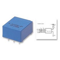
... Voltage Transducer LV 25-P/SP2 For the electronic measurement of voltages : DC, AC, pulsed..., with a galvanic isolation between the primary circuit (high voltage) and the secondary circuit (electronic circuit). 16073 Electrical data I Primary nominal r.m.s. current PN I Primary current, measuring range P R Measuring resistance M with ± ± ...

Page 2

... General tolerance Fastening & connection of primary Fastening & connection of secondary 3 pins Recommended PCB hole Instructions for use of the voltage transducer model LV 25-P/SP2 Primary resistor R : the transducer’s optimum accuracy is obtained at the nominal primary current. As far as possible calculated so that the nominal voltage to be measured corresponds to a primary current of 10 mA. ...

Related keywords