MLG1608B6N8DT TDK Corporation, MLG1608B6N8DT Datasheet
MLG1608B6N8DT
Manufacturer Part Number
MLG1608B6N8DT
Description
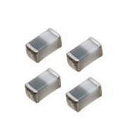
RF Inductors 6.8nH +-0.5NH
Manufacturer
TDK Corporation
Datasheet
1.MLG1608B2N7ST.pdf
(4 pages)
Specifications of MLG1608B6N8DT
Inductance
6.8 nH
Tolerance
0.5 nH
Maximum Dc Current
600 mAmps
Maximum Dc Resistance
0.18 Ohms
Self Resonant Frequency
4.5 MHz
Q Minimum
10
Operating Temperature Range
- 55 C to + 125 C
Termination Style
SMD/SMT
Lead Free Status / Rohs Status
Details
Other names
MLG1608B6N8D
Available stocks
Company
Part Number
Manufacturer
Quantity
Price
Company:

Part Number:
MLG1608B6N8DT
Manufacturer:
TDK
Quantity:
4 550
Company:
Part Number:
MLG1608B6N8DT000
Manufacturer:
TDK
Quantity:
108 862
Part Number:
MLG1608B6N8DT000
Manufacturer:
SMD0603
Quantity:
20 000
Company:
Part Number:
MLG1608B6N8DTD25
Manufacturer:
TDK
Quantity:
60 000


SMD Inductors(Coils)
For High Frequency(Multilayer)
MLG Series MLG1608
FEATURES
• Inductance values are supported from 1 to 1000nH.
• Advanced monolithic structure is formed using a multilayering
• The products contain no lead and also support lead-free
• It is a product conforming to RoHS directive.
APPLICATIONS
For high-frequency applications including mobile phones, high
frequency modules (PA, VCO, FEM etc.), Bluetooth, W-LAN, UWB
and tuners.
SHAPES AND DIMENSIONS
RECOMMENDED PC BOARD PATTERN
RECOMMENDED SOLDERING CONDITION
REFLOW SOLDERING
• Conformity to RoHS Directive: This means that, in conformity with EU Directive 2002/95/EC, lead, cadmium, mercury, hexavalent chromium, and specific
• Please contact our Sales office when your application are considered the following:
• All specifications are subject to change without notice.
250 to 260˚C
230˚C
180˚C
150˚C
The device’s failure or malfunction may directly endanger human life (e.g. application for automobile/aircraft/medical/nuclear power devices, etc.)
bromine-based flame retardants, PBB and PBDE, have not been used, except for exempted applications.
and sintering process with ceramic and conductive materials for
high-frequency.
soldering.
0.6
0.8
Preheating
60 to 120s
0.3±0.2
1.6±0.15
0.6
Time(s)
Dimensions in mm
Soldering
30 to 60s
10s max.
Natural
cooling
Weight: 4mg
PRODUCT IDENTIFICATION
(1) Series name
(2) Dimensions
(3) Material code
(4) Inductance value
(5) Inductance tolerance
(6) Packaging style
SPECIFICATIONS
Operating temperature range
Storage temperature range
PACKAGING STYLE AND QUANTITIES
Packaging style
Taping
HANDLING AND PRECAUTIONS
• Before soldering, be sure to preheat components.
• After mounting components onto the printed circuit board, do not
• When hand soldering, apply the soldering iron to the printed
MLG 1608 B 2N2 S
(1)
The preheating temperature should be set so that the
temperature difference between the solder temperature and
product temperature does not exceed 150°C.
apply stress through board bending or mishandling.
circuit board only. Temperature of the iron tip should not exceed
300°C. Soldering time should not exceed 3 seconds.
1608
2N2
12N
R10
1R0
S
D
J
T
(2)
(3) (4)
(5) (6)
T
–55 to +125°C
–55 to +125°C
006-05 / 20090921 / e521_mlg1608.fm
1.6× 0.8mm (L× W)
2.2nH
12nH
100nH
1000nH
±0.3nH
±0.5nH
±5%
Taping (reel)
Quantity
4000 pieces/reel
Conformity to RoHS Directive
(1/4)
Related parts for MLG1608B6N8DT
Image
Part Number
Description
Manufacturer
Datasheet
Request
R

Part Number:
Description:
TDK DC to DC Converters, DC to AC Inverters
Manufacturer:
TDK Corporation
Datasheet:
Part Number:
Description:
TDK DC to DC Converters, DC to AC Inverters
Manufacturer:
TDK Corporation
Datasheet: