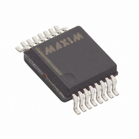
MAX1452AAE+ Maxim Integrated Products, MAX1452AAE+ Datasheet - Page 6

MAX1452AAE+
Manufacturer Part Number
MAX1452AAE+
Description
IC SENSOR SIGNAL COND 16-SSOP
Manufacturer
Maxim Integrated Products
Type
Signal Conditionerr
Datasheet
1.MAX1452CAE.pdf
(25 pages)
Specifications of MAX1452AAE+
Input Type
Analog
Output Type
Analog
Interface
Serial
Current - Supply
2.5mA
Mounting Type
Surface Mount
Package / Case
16-SSOP
Bandwidth
1.15MHz
Supply Voltage Min
4.5V
Supply Voltage Max
5.5V
Digital Ic Case Style
SSOP
No. Of Pins
16
Operating Temperature Range
-40°C To +125°C
Supply Voltage Range
4.5V To 5.5V
Rohs Compliant
Yes
Lead Free Status / RoHS Status
Lead free / RoHS Compliant
The MAX1452 provides amplification, calibration, and
temperature compensation to enable an overall perfor-
mance approaching the inherent repeatability of the
sensor. The fully analog signal-path introduces no
quantization noise in the output signal while enabling
digitally controlled trimming with the integrated 16-bit
DACs. Offset and span can be calibrated to within
±0.02% of span.
The MAX1452 architecture includes a programmable
sensor excitation, a 16-step programmable-gain ampli-
fier (PGA), a 768-byte (6144 bits) internal EEPROM, four
16-bit DACs, an uncommitted op amp, and an on-chip
temperature sensor.The MAX1452 also provides a
unique temperature compensation strategy for offset
TC and FSOTC that was developed to provide a
remarkable degree of flexibility while minimizing testing
costs.
The customer can select from one to 114 temperature
points to compensate their sensor. This allows the lati-
tude to compensate a sensor with a simple first order
linear correction or match an unusual temperature
curve. Programming up to 114 independent 16-bit EEP-
ROM locations corrects performance in 1.5°C tempera-
ture increments over a range of -40°C to +125°C. For
sensors that exhibit a characteristic temperature perfor-
mance, a select number of calibration points can be
used with a number of preset values that define the
temperature curve. In cases where the sensor is at a
different temperature than the MAX1452, the MAX1452
uses the sensor bridge itself to provide additional tem-
perature correction.
Low-Cost Precision Sensor
Signal Conditioner
6
_______________________________________________________________________________________
SSOP/TSSOP
10
11
12
13
14
15
16
—
9
PIN
Detailed Description
TQFN-EP
11
12
14
15
17
18
19
21
—
UNLOCK
AMPOUT
CLK1M
FSOTC
NAME
AMP+
V
AMP-
DIO
DDF
EP
Positive Supply Voltage for EEPROM. Connect a 1µF capacitor from
V
connect a 30Ω resistor to V
Secure-Lock Disable. Allows communication to the device.
Digital Input Output. DIO allows communication with the device.
1MHz Clock Output. The output can be controlled by a configuration bit.
Uncommitted Amplifier Output
Uncommitted Amplifier Negative Input
Uncommitted Amplifier Positive Input
Full Span TC Buffered Output
Exposed Pad (TQFN Only). Internally connected; connect to V
DDF
to V
SS
The single pin, serial Digital Input-Output (DIO) commu-
nication architecture and the ability to timeshare its
activity with the sensor’s output signal enables output
sensing and calibration programming on a single line
by parallel connecting OUT and DIO. The MAX1452
provides a Secure-Lock feature that allows the cus-
tomer to prevent modification of sensor coefficients and
the 52-byte user definable EEPROM data after the sen-
sor has been calibrated. The Secure-Lock feature also
provides a hardware override to enable factory rework
and recalibration by assertion of logic high on the
UNLOCK pin.
The MAX1452 allows complete calibration and sensor
verification to be performed at a single test station.
Once calibration coefficients have been stored in the
MAX1452, the customer can choose to retest in order to
verify performance as part of a regular QA audit or to
generate final test data on individual sensors.
The MAX1452’s low current consumption and the inte-
grated uncommitted op amp enables a 4–20mA output
signal format in a sensor that is completely powered
from a 2-wire current loop. Frequency response can be
user-adjusted to values lower than the 3.2kHz band-
width by using the uncommitted op amp and simple
passive components.
The MAX1452 (Figure 1) provides an analog amplifica-
tion path for the sensor signal. It also uses an analog
architecture for first-order temperature correction. A
digitally controlled analog path is then used for nonlin-
ear temperature correction. Calibration and correction
is achieved by varying the offset and gain of a pro-
grammable-gain-amplifier (PGA) and by varying the
. Connect V
Pin Description (continued)
DDF
DD
to V
.
FUNCTION
DD
or for improved noise performance
SS
.


