2222 123 15109 Vishay, 2222 123 15109 Datasheet - Page 10
2222 123 15109
Manufacturer Part Number
2222 123 15109
Description
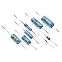
CAPACITOR ALUM ELECT 10UF, 16V, AXIAL
Manufacturer
Vishay
Datasheet
1.MAL212317101E3.pdf
(12 pages)
Specifications of 2222 123 15109
Capacitance
10µF
Capacitance Tolerance
± 20%
Voltage Rating
16V
Esr
8ohm
Life Time @ Temperature
20000 Hours @ 125°C
Height
15.3mm
Diameter
6.7mm
Capacitor Mounting
Through Hole
Rohs Compliant
No


123 SAL-A
Vishay BCcomponents
EQUIVALENT SERIES RESISTANCE (ESR)
Table 3
www.vishay.com
260
ESR
(Ω)
10
10
TEST PROCEDURES AND REQUIREMENTS
Endurance
Useful life
Shelf life
(storage at high
temperature)
Charge and
discharge
Shock
Severe rapid change
of temperature
Solvent resistance
Passive flammability
10
10
-1
-2
NAME OF TEST
1
2
1
Fig.28 Typical ESR as a function of ambient temperature
Case Ø D x L = 9.4 x 23.3 mm
1
2
3
4
10
TEST
10
IEC 60384-4/
EN130300
subclause 4.13
CECC 30302
subclause 1.8.1
IEC 60384-4/
EN130300
subclause 4.17
IEC 60384-4-2
subclause 9.21
IEC 60068-2-27
test Ea
IEC 60068-2-45,
test XA
IEC 60653
IEC 60695-2-2
2
REFERENCE
10
3
For technical questions, contact: aluminumcaps2@vishay.com
Curve 1: 68 µF, 35 and 40 V
Curve 2: 150 µF, 25 V
Curve 3: 330 µF, 10 V
Curve 4: 470 µF, 10 V
10
4
ESR at 100 Hz
T
U
U
10 000 hours
T
U
U
20 000 hours
T
500 hours
10
0.5 s to U
0.5 s to ground
half-sine or saw tooth pulse shape; 50 g; 11 ms;
3 successive shocks in each direction of
3 mutually perpendicular axes;
no voltage applied
100 cycles of 1 hour duration, each with
30 minutes at - 40 °C and + 125 °C
immersion:
5 ± 0.5 minutes with or without ultrasonic
at 55 ± 5 °C
solvents: demineralized water and/or calgonite
solution (20 g/l)
capacitor mounted to a vertical printed-circuit
board, one flame on capacitor body;
T
test duration = 20 s
amb
amb
amb
amb
R
R
R
R
10
6
= 6.3 to 25 V with U
= 35 and 40 V with U
= 6.3 to 25 V with U
= 35 and 40 V with U
cycles without series resistance:
5
= 125 °C;
= 125 °C; I
= 125 °C; no voltage applied;
= 20 to 25 °C;
f (Hz)
Aluminum Capacitors
R
;
10
Solid Axial
(quick refeerence)
6
R
PROCEDURE
applied and
R
R
ESR
(Ω)
10
10
C
C
10
applied;
applied;
10
applied;
applied;
-1
-2
1
2
1
Fig.29 Typical ESR as a function of ambient temperature
1
2
3
4
5
Case Ø D x L = 9.4 x 23.3 mm
10
10
2
ΔC/C: ± 10 %
tan δ ≤ 1.2 x spec. limit
Z ≤ 1.2 x spec. limit
I
ΔC/C: ± 15 %
tan δ ≤ 1.5 x spec. limit
Z ≤ 1.5 x spec. limit
I
no short or open circuit,
no visible damage
total failure percentage: < 1 %
ΔC/C: ± 10 %
tan δ ≤ 1.2 x spec. limit
I
ΔC/C: ± 5 %
no short or open circuit,
no visible damage
no intermittent contacts
no breakdown
no open circuiting
no mechanical damage
ΔC/C: ± 5 %
tan δ ≤ 1.2 x spec. limit
Z ≤ 1.2 x spec. limit
I
ΔC/C: ± 25 %
tan δ ≤ 1.5 x spec. limit
Z ≤ 2.0 x spec. limit
I
visual appearance not affected
after removing the test flame from the
capacitor, the capacitor must not
continue to burn for more than 15 s;
no burning particles must drop from
the sample
L5
L5
L5
L5
L5
Curve 3: 220 µF, 25 V
Curve 4: 470 µF, 16 V
Curve 5: 680 µF, 10 V; 1000 µF, 6.3 V
Curve 1: 100 µF, 35 and 40 V
Curve 2: 150 µF, 35 V
≤ spec. limit
≤ spec. limit
≤ 1 x spec. limit
≤ 1.5 x spec. limit
≤ 1 x spec.limit
10
3
REQUIREMENTS
Document Number: 28355
10
4
Revision: 23-Jun-08
ESR at 100 Hz
10
5
f (Hz)
10
6
Related parts for 2222 123 15109
Image
Part Number
Description
Manufacturer
Datasheet
Request
R

Part Number:
Description:
CAPACITOR ALUM ELECT 10UF, 35V, AXIAL
Manufacturer:
Vishay
Datasheet:

Part Number:
Description:
CAPACITOR ALUM ELECT 2.2UF, 35V, AXIAL
Manufacturer:
Vishay
Datasheet:
Part Number:
Description:
CAPACITOR ALUM ELECT 4.7UF, 35V, AXIAL
Manufacturer:
Vishay
Datasheet:
Part Number:
Description:
CAPACITOR ALUM ELECT 22UF, 16V, AXIAL
Manufacturer:
Vishay
Datasheet:
Part Number:
Description:
CAPACITOR ALUM ELECT 10UF, 40V, AXIAL
Manufacturer:
Vishay
Datasheet:
Part Number:
Description:
CAPACITOR ALUM ELECT 4.7UF, 40V, AXIAL
Manufacturer:
Vishay
Datasheet:

Part Number:
Description:
Capacitor,1000uF,10VDC,20-% Tol,20+% Tol
Manufacturer:
Vishay
Part Number:
Description:
Capacitor,220uF,25VDC,20-% Tol,20+% Tol
Manufacturer:
Vishay
Part Number:
Description:
Capacitor,330uF,25VDC,10-% Tol,10+% Tol
Manufacturer:
Vishay
Part Number:
Description:
357-036-542-201 CARDEDGE 36POS DL .156 BLK LOPRO
Manufacturer:
Vishay
Datasheet:
Part Number:
Description:
357-036-542-201 CARDEDGE 36POS DL .156 BLK LOPRO
Manufacturer:
Vishay
Datasheet:
Part Number:
Description:
357-036-542-201 CARDEDGE 36POS DL .156 BLK LOPRO
Manufacturer:
Vishay
Datasheet:
Part Number:
Description:
357-036-542-201 CARDEDGE 36POS DL .156 BLK LOPRO
Manufacturer:
Vishay
Datasheet:
Part Number:
Description:
357-036-542-201 CARDEDGE 36POS DL .156 BLK LOPRO
Manufacturer:
Vishay
Datasheet: