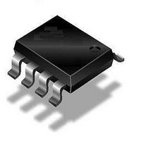
QT115A-ISG Atmel, QT115A-ISG Datasheet - Page 35

QT115A-ISG
Manufacturer Part Number
QT115A-ISG
Description
IC TOUCH SENSOR PROX 8SOIC
Manufacturer
Atmel
Datasheet
1.AT42QT1040-MMH.pdf
(72 pages)
Specifications of QT115A-ISG
Input Type
*
Output Type
*
Interface
*
Current - Supply
*
Mounting Type
Surface Mount
Operating Supply Voltage
3 V to 5 V
Maximum Operating Temperature
+ 85 C
Mounting Style
SMD/SMT
Package / Case
SO-8
Minimum Operating Temperature
- 40 C
Lead Free Status / RoHS Status
Lead free / RoHS Compliant
Package / Case
-
Lead Free Status / Rohs Status
Details
4.2.2.5
4.2.2.6
4.2.2.7
Touch Sensors Design Guide
Coupling Length
Calculations for the X Electrode
Example Calculation
The goal with this interdigitated design is to optimize SNR by maximizing the coupling length
the X and Y electrodes within the confines of the space allocated for the key. The coupling length is
determined by a combination of the number of X and Y fingers, their individual widths, and the spacing
between them; several thin fingers means a longer coupling length than a few wide ones, which results
in a better SNR.
Given the widths of the Y and X traces, you will need to calculate the number of X fingers (X
will fit in the digitated electrode, allowing for a border at least T wide. Note that any unallocated width
remaining after the number of fingers has been calculated must be added to the border, so the width of
the border (X
Equation 4-6
definitions).
Equation 4-6. Calculation for X
If the following measurements are used:
then the calculations using
This results in the pattern shown in
1. That is, the total length of the facing edge between the X and Y electrodes.
border
gives the equations that can be used to calculate X
X
X
Where:
T = 0.5 mm
W = 10 mm
H = 8 mm
Y
X
X
) must also be calculated.
fingers
border
width
fingers
border
number; that is, round down to the nearest integer. For example,
...
=0.1 mm
= (W - T - Y
=
is the FLOOR operator, defined as the largest integer not greater than the
W - 3T - Y
Equation 4-6
=
=
=
= 9
= (10 - 0.5 - 0.1 - 9 x (0.75 + 0.1)) / 2
= (9.4 - 7.65) / 2
= 0.875 mm
fingers
(10 - 1.5 - 0.1) / (0.75 + 0.1)
8.4 / 0.85
9.88
width
Figure 4-3 on page
width
and X
- X
is as follows:
) / (1.5T + Y
fingers
border
(1.5T + Y
width
Mutual-capacitance Zero-dimensional Sensors
4-4.
width
)
)) / 2
fingers
and X
border
(see
6.6
10620D–AT42–04/09
Figure 4-2
is 6.
(1)
fingers
between
) that
4-3
for


