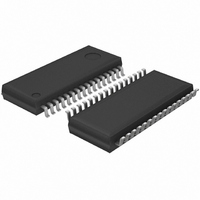
BU21050FS-E2 Rohm Semiconductor, BU21050FS-E2 Datasheet - Page 3

BU21050FS-E2
Manufacturer Part Number
BU21050FS-E2
Description
IC CAP SENSOR SWITCH 8CH 32-SSOP
Manufacturer
Rohm Semiconductor
Type
Capacitive Switchr
Specifications of BU21050FS-E2
Package / Case
32-SSOP
Input Type
Logic
Output Type
Logic
Interface
Port
Current - Supply
550µA
Mounting Type
Surface Mount
Supply Current
550µA
Supply Voltage Range
4.5V To 5.5V
Sensor Case Style
SSOP
No. Of Pins
32
Operating Temperature Range
-40°C To +85°C
Svhc
No SVHC (18-Jun-2010)
Base
RoHS Compliant
Supply Voltage
5 V
Dimensions
13.6 mm L x 7.8 mm W x 1.8 mm H
Power Dissipation
760 mW
Temperature Range
- 55 C to + 125 C
Termination Style
SMD/SMT
Base Number
21050
Rohs Compliant
Yes
Lead Free Status / RoHS Status
Lead free / RoHS Compliant
Lead Free Status / RoHS Status
Lead free / RoHS Compliant
Other names
BU21050FS-E2TR
●Block Diagram, Pin configuration
© 2009 ROHM Co., Ltd. All rights reserved.
BU21050FS
www.rohm.com
・Sensor I/F CV Conversion Circuit
・AD Conversion
・Conversion Sequence Control
・Noise Filter
・Compare threshold
・Interface Selection
・Calibration
・Reset Generation
・Clock Generation
This part selects target sensor and converts its capacitance to a voltage signal. Specifically, all eight sensors are selected
one-by-one and their capacity is compared to a common referencecapacity. Each difference value is converted to a certain
voltage signal.
The voltage signal derived from CV conversion is further converted to digital value by this block.
This block controls the process of CV conversion and generates timing of selecting target sensors.
The GND level difference between appliance and human body will cause noises to the CVconversion circuit.
This block eliminates these noises.
By setting this block, output mode can be set to either 8-bit PIO mode or 4-bit binary mode.
When the capacitance change do not exceed the threshold for a certain period, this block
tarts-up calibration process.
This is internal reset circuit. Reset is initialized by external SDN signal.
Clock from internal RC oscillation circuit is used as system clock.
CV converted to sensor data On / Off compared with a threshold, the switch converts the signal.
3/7
Technical Note
2009.04 - Rev.B


