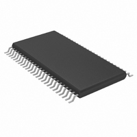
MAX9213EUM+D Maxim Integrated Products, MAX9213EUM+D Datasheet - Page 5

MAX9213EUM+D
Manufacturer Part Number
MAX9213EUM+D
Description
IC SERIALIZER PROG 48-TSSOP
Manufacturer
Maxim Integrated Products
Datasheet
1.MAX9209EUMD.pdf
(21 pages)
Specifications of MAX9213EUM+D
Function
Serializer
Data Rate
1.785Gbps
Input Type
LVTTL/LVCMOS
Output Type
LVDS
Number Of Inputs
21
Number Of Outputs
3
Voltage - Supply
3 V ~ 3.6 V
Operating Temperature
-40°C ~ 85°C
Mounting Type
Surface Mount
Package / Case
48-TSSOP
Lead Free Status / RoHS Status
Lead free / RoHS Compliant
AC ELECTRICAL CHARACTERISTICS (continued)
(V
are at V
Note 1: Current into a pin is defined as positive. Current out of a pin is defined as negative. All voltages are referenced to ground
Note 2: Maximum and minimum limits over temperature are guaranteed by design and characterization. Devices are production
Note 3: Guaranteed by design.
Note 4: TCIP is the period of TxCLK IN.
Note 5: AC parameters are guaranteed by design and characterization, and are not production tested. Limits are set at ±6 sigma.
Note 6: Pulse position TPPosN is characterized using 2
(V
TxCLK IN High Time
TxCLK IN Low Time
TxIN to TxCLK IN Setup
TxIN to TxCLK IN Hold
TxCLK IN to TxCLK OUT Delay
Serializer Phase-Locked Loop Set
Serializer Power-Down Delay
TxCLK IN Cycle-to-Cycle Jitter
(Input Clock Requirement)
Magnitude of Differential Output
Voltage
CC
CC
100
80
60
40
20
= +3.0V to +3.6V, R
= +3.3V, R
CC
0
except V
tested at T
MAX9209
DC-BALANCED MODE
WORST-CASE PATTERN AND PRBS
SUPPLY CURRENT vs. FREQUENCY
PARAMETER
= +3.3V, T
10
L
WORST-CASE
PATTERN
OD
= 100Ω ±1%, C
FREQUENCY (MHz)
A
20
, ΔV
_______________________________________________________________________________________
A
= +25°C.
= +25°C.) (Notes 4, 5)
OD
L
30
= 100Ω ±1%, C
, and ΔV
2
7
- 1 PRBS
L
40
= 5pF, PWRDWN = high, T
OS
SYMBOL
.
TPLLS
TCCD
THTC
TPDD
TSTC
TCIH
50
TCIL
V
TJIT
OD
L
= 5pF, PWRDWN = high, DCB/NC = high or low, unless otherwise noted. Typical values
100
Figure 7
Figure 7
Figure 7
Figure 7
Non-DC-balanced mode, Figure 8
DC-balanced mode, Figure 8
Figure 9
Figure 10
595Mbps data rate, worst-case
pattern
80
60
40
20
0
MAX9209
NON-DC-BALANCED MODE
SUPPLY CURRENT vs. FREQUENCY
WORST-CASE PATTERN AND PRBS
Programmable DC-Balanced
7
10
- 1 PRBS data.
CONDITIONS
A
FREQUENCY (MHz)
20
WORST-CASE
PATTERN
= +25°C, unless otherwise noted.)
30
Typical Operating Characteristics
40
2
7
- 1 PRBS
50
60
21-Bit Serializers
0.3 x TCIP
0.3 x TCIP
MIN
250
2.2
3.5
4.7
120
100
0
80
60
40
20
WORST-CASE AND PRBS SUPPLY CURRENT
15
MAX9213
NON-DC-BALANCED MODE
30
TYP
4.5
5.9
14
vs. FREQUENCY
WORST-CASE
PATTERN
FREQUENCY (MHz)
45
0.7 x TC IP
0.7 x TC IP
32800 x
MAX
TCIP
6.0
7.2
60
50
2
2
7
- 1 PRBS
75
UNITS
mV
ns
ns
ns
ns
ns
ns
ns
ns
90
5


