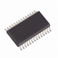
MAX336CWI+ Maxim Integrated Products, MAX336CWI+ Datasheet

MAX336CWI+
Specifications of MAX336CWI+
Related parts for MAX336CWI+
MAX336CWI+ Summary of contents
Page 1
... DIP/SO/SSOP N. INTERNAL CONNECTION Rail-to-Rail is a registered trademark of Nippon Motorola Ltd. ________________________________________________________________ Maxim Integrated Products For free samples & the latest literature: http://www.maxim-ic.com, or phone 1-800-998-8800 16-Channel/Dual 8-Channel, ____________________________Features <400Ω (max) On-Resistance <500ns Transition Time <10Ω On-Resistance Match <20pA NO-Off Leakage Current at +25°C 3 ...
Page 2
Low-Leakage, CMOS Analog Multiplexers ABSOLUTE MAXIMUM RATINGS Voltage Referenced ............................................................................-0.3V, 44V GND .........................................................................-0.3V, 25V Digital Inputs, A_, EN_, NO, COM (Note 1).............................................(V- - 0.3V) to (V+ + 0.3V) or 30mA (whichever occurs first) Continuous Current ...
Page 3
Low-Leakage, CMOS Analog Multiplexers ELECTRICAL CHARACTERISTICS—Dual Supplies (continued) (V+ = +15V -15V, GND = 0V PARAMETER SYMBOL INPUT Input Current with I AH Input Voltage High Input Current with I AL Input Voltage Low SUPPLY Power-Supply ...
Page 4
Low-Leakage, CMOS Analog Multiplexers ELECTRICAL CHARACTERISTICS—Single Supply (V+ = +12V 0V, GND = 0V +2.4V PARAMETER SYMBOL SWITCH Analog Signal Range V COM On-Resistance R ON DYNAMIC Transition Time ...
Page 5
Low-Leakage, CMOS Analog Multiplexers ____________________________Typical Operating Characteristics (continued +25°C, unless otherwise noted.) A ON-RESISTANCE vs. V COM 700 600 V± = ±5V 500 400 V± = ±15V V± = ±10V 300 200 100 V± = ±20V 0 -20 ...
Page 6
Low-Leakage, CMOS Analog Multiplexers ______________________________________________________________Pin Description PIN MAX336 MAX337 13, 14 — 2 4–11 — NO16-NO9 — 4–11 NO8B–NO1B 12 12 14–17 — — 15, 16, 17 A2, A1 ...
Page 7
Low-Leakage, CMOS Analog Multiplexers ______________________________________________Test Circuits/Timing Diagrams +15V NO2–NO15 A0 MAX336 +2.4V GND 50 -15V +15V NO1A–NO8A, MAX337 +2.4V GND 50 -15V Figure 2. Transition Time ...
Page 8
Low-Leakage, CMOS Analog Multiplexers _________________________________Test Circuits/Timing Diagrams (continued) +15V V+ +2.4V EN NO1–NO16 A0 A1 MAX336 A2 A3 GND V- 50 -15V Figure 4. Break-Before-Make Interval +15V R S NO1–NO16 EN MAX336 CHANNEL SELECT ...
Page 9
Low-Leakage, CMOS Analog Multiplexers _________________________________Test Circuits/Timing Diagrams (continued) +15V 10nF +2. NO2 NO16 A0 MAX336 GND 10nF V OUT OFF ISOLATION = 20log V IN Figure 6. Off Isolation ...
Page 10
Low-Leakage, CMOS Analog Multiplexers ________Pin Configurations/Functional Diagrams/Truth Tables (continued) TOP VIEW COMB NO8B 4 25 NO7B 24 5 MAX337 NO6B 6 23 NO5B 7 22 NO4B 8 21 NO3B 9 ...
Page 11
Low-Leakage, CMOS Analog Multiplexers __Ordering Information (continued) PART TEMP. RANGE MAX336EPI -40°C to +85°C MAX336EWI -40°C to +85°C MAX336EAI -40°C to +85°C MAX336EJI -40°C to +85°C MAX336MJI -55°C to +125°C MAX337CPI 0°C to +70°C MAX337CWI 0°C to +70°C MAX337CAI 0°C ...
Page 12
... Maxim cannot assume responsibility for use of any circuitry other than circuitry entirely embodied in a Maxim product. No circuit patent licenses are implied. Maxim reserves the right to change the circuitry and specifications without notice at any time. 12 __________________Maxim Integrated Products, 120 San Gabriel Drive, Sunnyvale, CA 94086 (408) 737-7600 © 1997 Maxim Integrated Products Printed USA ...


