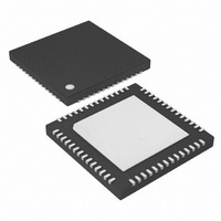
MAX4927ETN+ Maxim Integrated Products, MAX4927ETN+ Datasheet

MAX4927ETN+
Specifications of MAX4927ETN+
Related parts for MAX4927ETN+
MAX4927ETN+ Summary of contents
Page 1
... Low 450µA (max) Quiescent Current ♦ Bidirectional Multiplexer/Demultiplexer ♦ Standard Pin Out, Matching the PI3L500-A and Applications STMUX1000L ♦ Space-Saving Lead-Free Package 56-Pin, 5mm x 11mm, TQFN Package PART MAX4927ETN+ +Denotes lead-free package. 28 GND Note: All devices are specified over the -40°C to +85°C operating ...
Page 2
Base-T, ±15kV ESD Protection LAN Switch ABSOLUTE MAXIMUM RATINGS V ………………………………………………………-0.3V to +4V DD All Other Pins…………………………………-0. Continuous Current (A_ to _B_) ......................................±120mA Continuous Current (LED_ to _LED_) .…………………… ±40mA Peak Current (A_ to _B_) (pulsed at ...
Page 3
Base-T ±15kV ESD Protection LAN Switch ELECTRICAL CHARACTERISTICS (continued +3V to +3.6V MIN PARAMETER SYMBOL SWITCH AC CHARACTERISTICS -3dB Bandwidth Off-Capacitance On-Capacitance Turn-On Time Turn-Off Time Propagation ...
Page 4
Base-T, ±15kV ESD Protection LAN Switch SEL 50 50% t OFF 50% Figure 2. Turn-On and Turn-Off Times A_ t PLH _B_ PULSE SKEW = SK(p) PHL PLH THE MAX4927 SWITCHES ...
Page 5
Base-T, ±15kV ESD Protection LAN Switch (V = 3.3V +25°C, unless otherwise noted ON-RESISTANCE vs +85° -40° +25° ...
Page 6
Base-T, ±15kV ESD Protection LAN Switch PIN NAME 13, 16, 21, 24, 28, 33, GND Ground 39, 44, 49, 53 Switch 0. Common terminal Switch 1. Common terminal 1. 4, ...
Page 7
Base-T, ±15kV ESD Protection LAN Switch PIN NAME 51 2LED2 2LED2 Output. Drive SEL high (SEL = 1) to connect LED2 to 2LED2. 52 2LED1 2LED1 Output. Drive SEL low (SEL = 0) to connect LED2 to 2LED1. 54 ...
Page 8
Base-T, ±15kV ESD Protection LAN Switch Human Body Model Figure 5a shows the Human Body Model. Figure 5b shows the current waveform it generates when dis- charged into a low impedance. This model consists of a 100pF capacitor charged ...
Page 9
Base-T, ±15kV ESD Protection LAN Switch 1MΩ 1500Ω DISCHARGE CHARGE-CURRENT- RESISTANCE LIMIT RESISTOR HIGH STORAGE VOLTAGE 100pF CAPACITOR DC SOURCE Figure 5a. Human Body ESD Test Model I 100 90% ...
Page 10
Base-T, ±15kV ESD Protection LAN Switch DOCKING STATION NOTEBOOK TRD0_P TRD0_N TRD1_P TRD1_N ETHERNET PHY/MAC TRD2_P TRD2_N TRD3_P TRD3_N LED_OUT SEL_DOCK 10 ______________________________________________________________________________________ CONNECTOR 0B2 1B2 2B2 3B2 4B2 A0 5B2 A1 6B2 7B2 A2 _LED2 A3 MAX4927 A4 ...
Page 11
Base-T, ±15kV ESD Protection LAN Switch LED0 LED1 LED2 SEL ______________________________________________________________________________________ Functional Diagram 0B1 1B1 0B2 1B2 2B1 3B1 2B2 3B2 4B1 5B1 4B2 5B2 6B1 7B1 6B2 7B2 0LED1 0LED2 ...
Page 12
Base-T, ±15kV ESD Protection LAN Switch (The package drawing(s) in this data sheet may not reflect the most current specifications. For the latest package outline information www.maxim-ic.com/packages.) 12 ______________________________________________________________________________________ Package Information ...
Page 13
... Maxim cannot assume responsibility for use of any circuitry other than circuitry entirely embodied in a Maxim product. No circuit patent licenses are implied. Maxim reserves the right to change the circuitry and specifications without notice at any time. Maxim Integrated Products, 120 San Gabriel Drive, Sunnyvale, CA 94086 408-737-7600 ____________________ 13 © 2007 Maxim Integrated Products Package Information (continued registered trademark of Maxim Integrated Products, Inc ...


