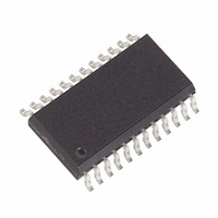
MAX4359EWG+ Maxim Integrated Products, MAX4359EWG+ Datasheet - Page 4

MAX4359EWG+
Manufacturer Part Number
MAX4359EWG+
Description
IC VIDEO CROSSPOINT SWIT 24SOIC
Manufacturer
Maxim Integrated Products
Datasheet
1.MAX4359EWG.pdf
(17 pages)
Specifications of MAX4359EWG+
Function
Video Crosspoint Switch
Circuit
1 x 4:4
Voltage Supply Source
Dual Supply
Voltage - Supply, Single/dual (±)
±4.5 V ~ 5.5 V
Operating Temperature
-40°C ~ 85°C
Mounting Type
Surface Mount
Package / Case
24-SOIC (0.300", 7.50mm Width)
Lead Free Status / RoHS Status
Lead free / RoHS Compliant
Low-Cost 4x4, 8x4, 8x8
Video Crosspoint Switches
4
4, 6, 8, 10
_______________________________________________________________________________________
3, 5
SO
11
12
13
14
15
—
1
2
7
9
MAX4359
12–16, 18,
4, 6, 8, 10
SSOP
19, 30
22–26
3, 5
11
17
20
21
1
2
7
9
4, 6, 8, 10,
12, 14, 16,
MAX4360
SSOP
19, 30
22–26
PIN
3, 5
18
11
17
20
21
1
2
7
9
5, 7, 9, 11,
13, 15, 17,
3, 4, 6
10, 12
20, 34
DIP
19
14
18
21
22
—
1
2
8
MAX4456
6, 8, 10, 13,
15, 17, 19,
1, 12, 23,
PLCC
4, 5, 7
11, 14
22, 38
21
16
34
20
24
25
2
3
9
D0/SER IN
SER OUT
SER/PAR
LATCH
NAME
DGND
EDGE/
LEVEL
LOAD
N.C.
D1/
IN_
WR
A_
V-
Video Input Lines
Parallel Data Bit D1 when SER/PAR = GND. Serial out-
put for cascading multiple parts when SER/PAR = V
Parallel Data Bit D0 when SER/PAR = GND. Serial
input when SER/PAR = V
Output Buffer Address Lines
Asynchronous Control Line. When LOAD = V
400Ω internal active loads are on. When LOAD = GND,
external 400Ω loads must be used. The buffers must
have a resistive load to maintain stability.
Digital Ground. DGND pins must have the same
potential and be bypassed to AGND. DGND should
be within ±0.3V of AGND.
When this control line is high, the 2nd-rank registers
are loaded with the rising edge of LATCH. If this con-
trol line is low, the 2nd-rank registers are transparent
when LATCH is low, passing data directly from the
1st-rank registers to the decoders.
No connection. Not internally connected.
Connect to V
parallel mode.
Negative Supply. All V- pins must be connected to each
other and bypassed to GND separately (Figure 2).
In serial mode, WR (write) shifts data into the input regis-
ter. In parallel mode, WR loads data into the 1st-rank
registers. Data is latched on the rising edge.
If EDGE/LEVEL = V
rank registers to the 2nd-rank registers on the rising
edge of LATCH. If EDGE/LEVEL = GND, data is
loaded while LATCH = GND. In addition, data is
loaded during the execution of parallel-mode func-
tions 1011 through 1110, or if LATCH = V
the execution of the parallel-mode “software-latch”
command (1111).
CC
for serial mode; connect to GND for
CC
FUNCTION
, data is loaded from the 1st-
CC
Pin Description
.
CC
CC
during
, all the
CC
.


