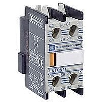
LA1KN11 SQUARE D, LA1KN11 Datasheet - Page 25

LA1KN11
Manufacturer Part Number
LA1KN11
Description
92F5946
Manufacturer
SQUARE D
Datasheet
1.9080MH339.pdf
(28 pages)
Specifications of LA1KN11
Leaded Process Compatible
No
Peak Reflow Compatible (260 C)
No
Rohs Compliant
No
For Use With
K-Line Contactors
04/01
Voltage Drop Caused by the Inrush Current (continued)
What cable c.s.a. is required for the control circuit of an CAD50G7 relay, operated from a distance of 500 meters.
CAD50G7, voltage 120 V, 60 Hz: inrush power: 70 VA.
On the left-hand graph on page 24, point X is at the intersection of the vertical line corresponding to 70 VA and the a 120 V (estimated) voltage curve.
On the right-hand graph on page 24 point Y is at the intersection of the vertical line corresponding to 500 m and the horizontal line passing through point X.
Use the conductor c.s.a. indicated by the curve which passes through point Y, between # 14 and # 16 AWG.
If point Y lies between two c.s.a. curves, choose the larger of the c.s.a. values. In this case # 14 AWG.
Calculating the maximum cable length
The maximum permissible length for acceptable line voltage drop is calculated by the formula:
Where:
L: distance between the contactor and the control device in m, (length of the cable),
U: supply voltage in V,
SA: apparent inrush power drawn by the coil in VA, (Vac) or W (Vdc)
s: conductor c.s.a. in mm
K: factor given in the table below.
a.c. supply
d.c. supply
L
=
U
------ - s.K.
SA
2
2
,
SA in VA
K
Irrespective of the inrush power SA, expressed in W
K = 1.38
©
2001 Schneider Electric All Rights Reserved
20
1.38
40
1.5
100
1.8
Long Distance Control Data
150
2
200
2.15
25


