HW1L-M1F10QD-R-24V IDEC, HW1L-M1F10QD-R-24V Datasheet - Page 54
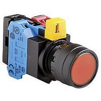
HW1L-M1F10QD-R-24V
Manufacturer Part Number
HW1L-M1F10QD-R-24V
Description
84C4595
Manufacturer
IDEC
Datasheet
1.HW1A-B1-R.pdf
(61 pages)
Specifications of HW1L-M1F10QD-R-24V
Contact Configuration
SPST-NO
Switch Operation
(On)
Contact Voltage Ac Nom
600V
Contact Voltage Dc Nom
220V
Contact Current Max
10A
Illumination Color
Red
Actuator Style
Round-Flush
Rohs Compliant
Yes


Oiltight Switches & Pilot Devices
ø40mm Head Push-Pull (HW1B-Y2)
Illuminated E-Stop Pushbuttons (HW1E-LV4)
Terminal Arrangement (Bottom View)
HW1E-BV4
Emergency Stop Stations
M3.5 Terminal Screw
Terminal Cover
Box Cover Mouting Screws
13
76
.2 (NC)
.1 (NC)
25.5
(1NO-1NC)
Side
.3 (NO)
.4 (NO)
TOP Marking
M3.5 Terminal Screw
Lamp Terminal
Panel Thickness 0.8 to 6
HW1B-V4R
Locking Ring
63
61
HW1E-LV4
Gasket
A
Box Cover
29.4
11.5
LAMP
USA: 800-262-IDEC
59.5
14
32
.2 (NC)
.1 (NC)
Box Base
(1NO-1NC)
TOP
X1
X2
.3 (NO)
.4 (NO)
ø40mm Head Unibody Pushlock Turn Reset (HW1B-BV4)
M3.5 Terminal Screw
Operator
Pushlock Turn Reset
Pushlock Key Reset
Push Pull
Terminal Cover
Canada: 888-317-IDEC
Panel Thickness 0.8 to 6
Dimension A (mm)
32
32 (Key inserted: 49.4)
25.5
Mounting Hole
Unit
HW1B-V3
HW1B-V4
HW1B-X4
HW1B-Y2
HW1B-V5
TOP Marking
Locking Ring
R0.8 max.
Gasket
46
48
Vertical Spacing
50 mm
60 mm
ø22mm - HW Series
3.2
11.5
+0.2
0
14
Mounting Hole Layout
The minimum mounting centers shown be-
low are applicable to E-Stop switches with
one layer of contact blocks (two contact
blocks). When two layers of contact blocks
are mounted, determine the minimum
mounting centers for ease of wiring.
4-M4 Tapped Holes for Rear Mounting
(Depth: 10 mm)
32
2-Front Mounting Holes
Horizontal Spacing
50 mm
60 mm
62
15.5
ø14 Knockout
Dimensions (mm)
553
Related parts for HW1L-M1F10QD-R-24V
Image
Part Number
Description
Manufacturer
Datasheet
Request
R

Part Number:
Description:
HW1L-M1F10Q-G-24V INC R/FL FV
Manufacturer:
IDEC
Datasheet:
Part Number:
Description:
HW1L-M1F10Q-R-24V INC R/FL FV
Manufacturer:
IDEC
Datasheet:
Part Number:
Description:
Cable; Between IDEC MicroSmart (port 1 or 2) and HG2F/3F/4F; 5 ft.
Manufacturer:
IDEC Corporation
Datasheet:
Part Number:
Description:
Cable; Between IDEC Micro^3C/ONC/MicroSmart (port 2) PLCs and HG2F/3F/4F; 5 ft.
Manufacturer:
IDEC Corporation
Datasheet:
Part Number:
Description:
Angled Key for Idec HS6B Safety Switch
Manufacturer:
IDEC Corporation
Datasheet:
Part Number:
Description:
Accessory, L-Shaped Key for Idec HS5B and HS5E Safety Switch
Manufacturer:
IDEC Corporation
Datasheet:
Part Number:
Description:
Accessory, Straight Key for Idec HS5B and HS5E Safety Switch
Manufacturer:
IDEC Corporation
Datasheet:
Part Number:
Description:
Straight Key for Idec HS6B Safety Switch
Manufacturer:
IDEC Corporation
Datasheet:
Part Number:
Description:
LIGHT TOWER 3 TIER RED/AMBER/GREEN 24VAC/DC WALL MOUNT
Manufacturer:
IDEC Corporation
Datasheet:
Part Number:
Description:
Flat Lens, 24V AC/DC, 1m Cable Length, Alternate: Red Green Color, IP67
Manufacturer:
IDEC Corporation
Datasheet:

Part Number:
Description:
INDICATOR INCANDESCENT LAMP, GREEN
Manufacturer:
IDEC
Datasheet:

Part Number:
Description:
LAMP, INDICATOR, INCAND, AMB
Manufacturer:
IDEC
Datasheet:
Part Number:
Description:
LAMP, INDICATOR, INCAND, GRN
Manufacturer:
IDEC
Datasheet:
Part Number:
Description:
LAMP, INDICATOR, INCAND, GRN
Manufacturer:
IDEC
Datasheet: