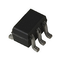
INA-31063 Avago Technologies US Inc., INA-31063 Datasheet

INA-31063
Specifications of INA-31063
Available stocks
Related parts for INA-31063
INA-31063 Summary of contents
Page 1
... With more than isolation to 2.5 GHz makes it an excellent candidate for LO buffer applications. The INA-31063 is fabricated using TM HP’s 30 GHz f ISOSAT MAX Silicon bipolar process which uses nitride self-alignment, submicrometer lithography, trench isolation, ion implantation, ...
Page 2
... Absolute Maximum Ratings Symbol Parameter V Device Voltage, d output to ground Input Power in T Junction Temperature j T Storage Temperature STG INA-31063 Electrical Specifications Symbol Parameters and Test Conditions Gain in 50 system 21 NF Noise Figure 50 P Output Power Gain Compression 1dB IP Output Third Order Intercept Point ...
Page 3
... INA-31063 Typical Performance 2.7 V 3 0.5 1.0 1.5 2.0 2.5 FREQUENCY (GHz) Figure 1. Gain vs. Frequency and Voltage measured system -40 C + 0.5 1.0 1.5 2.0 2.5 FREQUENCY (GHz) Figure 4. Gain vs. Frequency and Temperature measured system VSWR in VSWR out 0 0 0.5 1 ...
Page 4
... INA-31063 Typical Scattering Parameters Freq GHz Mag Ang dB 0.1 0.14 171 13.6 0.2 0.15 167 13.7 0.3 0.14 164 13.7 0.4 0.15 163 13.7 0.5 0.15 152 13.8 0.6 0.14 152 13.8 0.7 0.14 151 13.9 0.8 0.15 147 14.0 0.9 ...
Page 5
... INA-31063 Applications Information Introduction The INA-31063 volt silicon RFIC amplifier that is designed with a two stage internal network to provide a broadband gain and 50 input and 200 output impedance. With a P com pressed output power of -3 dBm and high isolation of 40 dB, the INA-31063 is well suited for LO buffer amplifier applications in mobile communication systems ...
Page 6
... None Output 2400 MHz 27 nH 1.8 nH None C out Figure 16. Suggested Matching Elements for Common Frequency Bands bypass The test results for the INA-31063 were measured on the 50 and output impedance matched amplifier described above. 4 900 MHz 1900 MHz -12 -16 -30 -25 ...
Page 7
... REFERENCE PLANES TEST CIRCUIT Figure 19. Phase Reference Planes. SOT-363 PCB Layout The INA-31063 is packaged in the miniature SOT-363 (SC-70) surface mount package. A PCB pad layout for the SOT-363 package is shown in Figure 20 (dimensions are in inches). This layout provides ample allowance ...
Page 8
... Storage & handling • Inspection & testing • Assembly • In-circuit use The INA-31063 is an ESD Class 1 device. Therefore, proper ESD precautions are recommended when handling, inspecting, testing, assembling, and using these devices to avoid damage. ...
Page 9
... BSC (0.025) 2.20 (0.087) 1.80 (0.071) 0.10 (0.004) 0.00 (0.00) 1.00 (0.039) 0.80 (0.031) 0.25 (0.010) 0.15 (0.006) DIMENSIONS ARE IN MILLIMETERS (INCHES) INA-31063 Part Number Ordering Information Part Number Devices per Container INA-31063-BLK 100 INA-31063-TR1 3,000 INA-31063-TR2 10,000 0.425 (0.017) TYP ...
Page 10
Tape Dimensions and Product Orientation For Outline DESCRIPTION CAVITY LENGTH WIDTH DEPTH PITCH BOTTOM HOLE DIAMETER PERFORATION DIAMETER PITCH POSITION CARRIER TAPE WIDTH THICKNESS COVER TAPE WIDTH TAPE THICKNESS DISTANCE CAVITY TO PERFORATION (WIDTH DIRECTION) ...
Page 11
Data subject to change. Copyright © 1999 Agilent Technologies Obsoletes 5967-5770E 5968-1238E (11/99) ...


