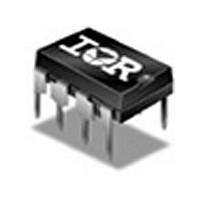
IR2161 International Rectifier, IR2161 Datasheet - Page 3

IR2161
Manufacturer Part Number
IR2161
Description
Halogen Converter Control IC in a 8-lead PDIP package. Features Auto Resetting Short Circuit Protection, Auto Resetting Overload Protection, Overtemperature Protection, Phase Cut Dimmable, Adaptive Deadtime, Output Voltage Shift Compensation and Soft
Manufacturer
International Rectifier
Datasheet
1.IR2161.pdf
(20 pages)
Specifications of IR2161
Number Of Drivers
2
Driver Type
High and Low Side
Rise Time
250ns
Fall Time
140ns
Frequency (max)
70KHz
Operating Supply Voltage (max)
16.5V
Peak Output Current
300mA
Power Dissipation
1W
Operating Supply Voltage (min)
11.5V
Operating Temp Range
-25C to 125C
Operating Temperature Classification
Commercial
Mounting
Through Hole
Pin Count
8
Package Type
PDIP
Package
8-pin DIP
Circuit
Electronic Transformer
Offset Voltage (v)
600
Pbf
PbF Option Available
Lead Free Status / Rohs Status
Not Compliant
Available stocks
Company
Part Number
Manufacturer
Quantity
Price
Part Number:
IR2161PBF
Manufacturer:
IR
Quantity:
20 000
Part Number:
IR2161S
Manufacturer:
IR
Quantity:
20 000
Part Number:
IR2161SPBF
Manufacturer:
IR
Quantity:
20 000
Company:
Part Number:
IR2161STRPBF
Manufacturer:
TOSHIBA
Quantity:
3 000
Part Number:
IR2161STRPBF
Manufacturer:
IR
Quantity:
20 000
www.irf.com
Voltage Compensation Characteristics (Run Mode)
Electrical Characteristics
V
Supply Characteristics
Floating Supply Characteristics
V
V
Symbol Definition
Symbol Definition
Symbol Definition
I
I
I
V
I
V
V
V
I
I
V
CCFLT
CC HF
I
BSLF
LEAK
CC
CC LF
QCCUV
BSHF
CSD (min)
CSD (max)
BSMIN
CCUV+
CCUV-
CCUVL-
CLAMP
= V
BS
= V
V
V
V
UVLO mode quiescent current
Fault-mode quiescent current
V
Offset supply leakage current
VCC current (low frequency)
VCC current (high frequency)
V
Min CSD voltage (in Run Mode)
Max CSD voltage (in Run Mode)
CC
CC
CC
CC
V
Minimum V
BIAS
BS
BS
threshold
threshold
threshold
supply undervoltage negative going
zener clamp voltage
supply undervoltage positive going
supply softstart reset negative going
low frequency supply current
high frequency supply current
= 14V, +/- 0.25V, VCSD = 5.0V, C
BS
to start oscillation at HO
LO =
C
Min.
HO
Min.
Min.
11.5
14.5
3.0
—
—
—
—
—
10
—
—
—
—
—
= 1000 pF, and T
Typ.
Typ.
Typ.
12.1
250
15.4
10.5
3.6
3.0
0.8
5.5
1.4
2.0
4.0
—
—
0
Max.
Max.
Max.
12.7
16.5
A
300
2.0
3.0
7.0
5.5
11
4.3
—
—
50
—
—
IR2161(
= 25 C unless otherwise specified.
Units Test Conditions
Units Test Conditions
Units Test Conditions
μA
μA
V
V
V
V
V
A
A
VCC=14V,VCSD=5.2V
V
VCC=14V,VBS=14V,
VCC=14V,VBS=14V,
I
CS=8V, VCSD=0V
VCC=14V,VCSD=0V
V
V
V
CC
S
CC
CC
CC
CC
VCSD=0V
VCSD=5.2V
V
VCS = 0V
VCS = 0.4V
) & (PbF)
B
= 5mA
- V
falling from 14V
= 11V
rising from 0V
= V
CCUV-
S
= 600V
(-2V)
3


