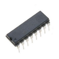
MC10H141P ON Semiconductor, MC10H141P Datasheet - Page 2

MC10H141P
Manufacturer Part Number
MC10H141P
Description
Counter Shift Registers 4-Bit Universal
Manufacturer
ON Semiconductor
Datasheet
1.MC10H141P.pdf
(6 pages)
Specifications of MC10H141P
Counting Sequence
Serial/Parallel to Parallel
Number Of Circuits
4
Package / Case
PDIP-16
Logic Family
10
Logic Type
ECL
Propagation Delay Time
2 ns
Supply Voltage (max)
5.46 V
Maximum Operating Temperature
+ 75 C
Minimum Operating Temperature
0 C
Function
Shift Register
Mounting Style
Through Hole
Operating Supply Voltage
- 8 V
Lead Free Status / Rohs Status
No RoHS Version Available
Available stocks
Company
Part Number
Manufacturer
Quantity
Price
Company:
Part Number:
MC10H141P
Manufacturer:
MOTOROLA
Quantity:
8
Part Number:
MC10H141P
Manufacturer:
MOTOROLA/摩托罗拉
Quantity:
20 000
Maximum ratings are those values beyond which device damage can occur. Maximum ratings applied to the device are individual stress limit
values (not normal operating conditions) and are not valid simultaneously. If these limits are exceeded, device functional operation is not implied,
damage may occur and reliability may be affected.
1. Each MECL 10H™ series circuit has been designed to meet the dc specifications shown in the test table, after thermal equilibrium has been
NOTE: Device will meet the specifications after thermal equilibrium has been established when mounted in a test socket or printed circuit
Table 2. MAXIMUM RATINGS
Table 3. ELECTRICAL CHARACTERISTICS
Table 4. AC PARAMETERS
Symbol
Symbol
established. The circuit is in a test socket or mounted on a printed circuit board and transverse air flow greater than 500 linear fpm is
maintained. Outputs are terminated through a 50 W resistor to −2.0 V.
V
V
V
t
f
T
I
V
I
I
V
t
t
hold
shift
T
V
out
inH
I
inL
set
stg
OH
pd
t
EE
OL
t
E
IH
A
IL
r
f
board with maintained transverse airflow greater than 500 lfpm. Electrical parameters are guaranteed only over the declared
operating temperature range. Functional operation of the device exceeding these conditions is not implied. Device specification limit
values are applied individually under normal operating conditions and not valid simultaneously.
I
Power Supply (V
Input Voltage (V
Output Current
Operating Temperature Range
Storage Temperature Range − Plastic
Power Supply Current
Input Current High
Input Current Low
High Output Voltage
Low Output Voltage
High Input Voltage
Low Input Voltage
Propagation Delay
Hold Time −
Set−up Time
Rise Time
Fall Time
Shift Frequency
Pins 5,6,9,11,12,13
Pins 7,10
Pin 4
Data, Select
Data
Select
Characteristic
CC
CC
= 0)
= 0)
− Continuous
− Surge
Characteristic
− Ceramic
(V
EE
= −5.2 V ±5% (Note 1)
http://onsemi.com
−1.02
−1.95
−1.17
−1.95
Min
250
0.5
1.0
1.0
1.5
3.0
0.5
0.5
−
−
−
−
0°
2
−0.84
−1.63
−0.84
−1.48
Max
405
416
510
112
2.0
2.4
2.4
−
−
−
−
−
−0.98
−1.95
−1.13
−1.95
Min
250
0.5
1.0
1.0
1.5
3.0
0.5
0.5
−
−
−
−
25°
−0.81
−1.63
−0.81
−1.48
Max
102
255
260
320
2.0
2.4
2.4
−
−
−
−
−
−55 to +150
−55 to +165
−8.0 to 0
0 to V
0 to +75
−0.92
−1.95
−1.07
−1.95
Rating
Min
250
0.3
1.1
1.0
1.5
3.0
0.5
0.5
100
−
−
−
−
50
EE
75°
−0.735
−0.735
−1.60
−1.45
Max
112
255
260
320
2.1
2.4
2.4
−
−
−
−
−
Unit
Vdc
Vdc
MHz
mA
Unit
Vdc
Vdc
Vdc
Vdc
°C
°C
°C
mA
mA
mA
ns
ns
ns
ns
ns


