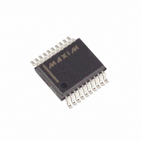
MAX4545CAP Maxim Integrated Products, MAX4545CAP Datasheet

MAX4545CAP
Specifications of MAX4545CAP
Available stocks
Related parts for MAX4545CAP
MAX4545CAP Summary of contents
Page 1
... SWITCHES SHOWN 1 ON FOR LOGIC “0” INPUT Rail-to-Rail is a registered trademark of Nippon Motorola Ltd. ________________________________________________________________ Maxim Integrated Products For free samples & the latest literature: http://www.maxim-ic.com, or phone 1-800-998-8800 Quad/Dual, Low-Voltage, Bidirectional RF/Video Switches ____________________________Features Low 50Ω Insertion Loss: -1dB at 100MHz High 50Ω ...
Page 2
Quad/Dual, Low-Voltage, Bidirectional RF/Video Switches ABSOLUTE MAXIMUM RATINGS (Voltages Referenced to GND) V+ ...........................................................................-0.3V, +13.0V V- ............................................................................-13.0V, +0. V-...................................................................-0.3V, +13.0V All Other Pins (Note 1) ..........................(V- - 0.3V) to (V+ + 0.3V) Continuous Current into Any Terminal..............................±25mA Peak ...
Page 3
ELECTRICAL CHARACTERISTICS—Dual Supplies (continued) (V+ = +4.5V to +5.5V -4.5V to -5.5V, V values are +25°C.) A PARAMETER SYMBOL SWITCH DYNAMIC CHARACTERISTICS Turn-On Time Turn-Off Time Break-Before-Make Time Delay (MAX4546/MAX4547 only) Charge Injection (Note 3) ...
Page 4
Quad/Dual, Low-Voltage, Bidirectional RF/Video Switches ELECTRICAL CHARACTERISTICS—Single +5V Supply (V+ = +4.5V to +5.5V 0V 0.8V, V INL +25°C.) A PARAMETER SYMBOL ANALOG SWITCH V COM_ Analog Signal Range V NO_ Signal-Path On-Resistance ...
Page 5
ELECTRICAL CHARACTERISTICS—Single +3V Supply (V+ = +2.7V to +3.6V 0V 0.8V, V INL +25°C.) A PARAMETER SYMBOL ANALOG SWITCH V Analog Signal Range V NO_ Signal-Path On-Resistance LOGIC INPUT IN_ Input Logic Threshold ...
Page 6
Quad/Dual, Low-Voltage, Bidirectional RF/Video Switches __________________________________________Typical Operating Characteristics (V+ = +5V -5V +25°C, GND = 0V, packages are surface mount, unless otherwise noted.) A ON-RESISTANCE vs. V COM (DUAL SUPPLIES) 100 V 1.2V, -1.2V ...
Page 7
Operating Characteristics (continued) (V+ = +5V -5V +25°C, GND = 0V, packages are surface mount, unless otherwise noted.) A LOGIC-LEVEL THRESHOLD vs. POSITIVE SUPPLY VOLTAGE 1.6 1.4 1.2 1.0 0.8 0.6 0.4 0 ...
Page 8
Quad/Dual, Low-Voltage, Bidirectional RF/Video Switches ______________________________________________________________Pin Description PIN MAX4545 MAX4546 MAX4547 1, 10 12 ...
Page 9
Typical attenuation in 50Ω systems is -1dB and is rea- sonably flat up to 100MHz. Higher-impedance circuits show even lower attenuation (and vice versa), but slightly lower bandwidth due to the increased effect of the internal and external capacitance and ...
Page 10
Quad/Dual, Low-Voltage, Bidirectional RF/Video Switches Single-supply operation also limits signal levels and interferes with grounded signals. When V- = 0V, AC sig- nals are limited to -0.3V. Voltages below -0.3V can be clipped by the internal ESD-protection diodes, and the ...
Page 11
V+ 10nF 12 V+ LOGIC 1 IN1 IN 2 COM1 3 GND1 GND1 50 IN/OUT MAX4546 NO1 4 6 NC4 7 GND4 8 COM4 10nF (61 V- LOGIC SWITCH 0 OFF 1 ON SWITCHES SHOWN FOR LOGIC ...
Page 12
Quad/Dual, Low-Voltage, Bidirectional RF/Video Switches 1 OUT MAX4545 ADDRESS DECODING MAX4545 MORE THAN 4 CHANNELS Figure 3. 4-Channel Multiplexer 12 ______________________________________________________________________________________ 1 OUT 2 50/75 ...
Page 13
Circuits/Timing Diagrams +5V 10nF V+ NO_OR NC_ MAX4545 MAX4546 MAX4547 V IN_ IN_ GND_ V- 50 10nF -5V REPEAT TEST FOR EACH SWITCH. Figure 4. Switching Time 10nF +5V V+ MAX4546 V IN_ IN_ GND_ 50 10nF * REPEAT ...
Page 14
Quad/Dual, Low-Voltage, Bidirectional RF/Video Switches _________________________________Test Circuits/Timing Diagrams (continued) 10nF +5V V+ NO_ OR NC_ MAX4545 MAX4546 MAX4547 V IN_ IN_ COM_ GND_ V- 50 10nF - CONNECTED TO GND (0V) FOR SINGLE-SUPPLY OPERATION. Figure 6. Charge Injection ...
Page 15
Test Circuits/Timing ______________Diagrams (continued) 10nF + IN_ NO_ NC_ MAX4545 MAX4546 MAX4547 COM_ GND_ V- 10nF -5V ALL GND_ PINS ARE CONNECTED TO GROUND PLANE (0V). Figure 8. NO_, NC_, COM_ Capacitance MAX4546 COM1 IN1 IN2 ...
Page 16
... Quad/Dual, Low-Voltage, Bidirectional RF/Video Switches ___________________________________________Ordering Information (continued) PART TEMP. RANGE MAX4545CAP 0°C to +70°C MAX4545C/D 0°C to +70°C MAX4545EPP -40°C to +85°C MAX4545EWP -40°C to +85°C MAX4545EAP -40°C to +85°C MAX4546CPE 0°C to +70°C MAX4546CSE 0°C to +70°C MAX4546CEE 0°C to +70°C MAX4546C/D 0° ...


