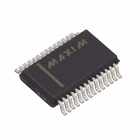
MAX4588CAI Maxim Integrated Products, MAX4588CAI Datasheet - Page 16

MAX4588CAI
Manufacturer Part Number
MAX4588CAI
Description
IC MUX DUAL RF VIDEO 4CH 28-SSOP
Manufacturer
Maxim Integrated Products
Series
4000r
Datasheet
1.MAX4588CAI.pdf
(20 pages)
Specifications of MAX4588CAI
Function
Video Multiplexer/Demultiplexer
Circuit
2 x 4:1
On-state Resistance
60 Ohm
Voltage Supply Source
Single, Dual Supply
Voltage - Supply, Single/dual (±)
2.7 V ~ 12 V, ± 2.7 V ~ 6 V
Operating Temperature
0°C ~ 70°C
Mounting Type
Surface Mount
Package / Case
28-SSOP
Lead Free Status / RoHS Status
Contains lead / RoHS non-compliant
Available stocks
Company
Part Number
Manufacturer
Quantity
Price
Part Number:
MAX4588CAI
Manufacturer:
MAXIM/美信
Quantity:
20 000
Company:
Part Number:
MAX4588CAI+
Manufacturer:
Maxim Integrated Products
Quantity:
135
Company:
Part Number:
MAX4588CAI+
Manufacturer:
MAX
Quantity:
44
The MAX4588 has internal circuitry to guarantee a
known state on power-up. In the default state, A0 = A1
= A2 = 0, disable = 1, and all switches are off. This
state is equivalent to asserting RS during normal opera-
tion.
The serial mode is activated by driving the SER/PAR
input pin to a logic high. The data is then entered using a
normal SPI/MICROWIRE write operation. Refer to Figure
7 for a detailed diagram of the serial-interface logic.
There are four flip-flops in the shift register, with the out-
put of the fourth shift register being output on the DOUT
pin. Note: DOUT changes on the rising edge of SCLK.
Low-Voltage, High-Isolation,
Dual 4-Channel RF/Video Multiplexer
Parallel Operation
x = Don’t Care
16
Note: 4/8 is not latched when LE is high. When LE is low, all latches are transparent. A2, A1, A0, and EN are latched.
SER/PAR
______________________________________________________________________________________
Connect COM1 to COM2 externally for 1-of-8 single-ended operation.
0
1
0
0
0
0
0
0
0
0
0
0
0
0
0
x
A2
x
x
x
x
0
0
0
0
1
1
1
1
x
x
x
x
Power-On Reset (POR)
A1
x
x
x
x
0
0
1
1
0
0
1
1
0
0
1
1
Serial Operation
A0
x
x
x
x
0
1
0
1
0
1
0
1
0
1
0
1
EN
x
x
x
0
1
1
1
1
1
1
1
1
1
1
1
1
LE
1
0
0
0
0
0
0
0
0
0
0
0
0
0
x
x
This allows cascading of multiple MAX4588s using only
one chip-select line. For example, one 16-bit write could
load the shift registers of four cascaded MAX4588s. The
data from the shift register is moved to the internal con-
trol latches only upon the rising edge of CS, so all four
MAX4588s change state simultaneously.
The parallel mode is activated by driving SER/PAR to a
logic low. The MAX4588 is programmed by a latched
parallel bus scheme. Refer to Figure 6 for a detailed
diagram of the parallel-interface logic. Note that 4/8 is
not latched. It is best to hard-wire 4/8 to a known state
for the desired mode of operation, or to use a dedicat-
ed microcontroller port pin.
RS
1
0
1
1
1
1
1
1
1
1
1
1
1
1
1
1
4/8 8
x
x
x
x
0
0
0
0
0
0
0
0
1
1
1
1
Maintain previous state.
All switches off, latches are cleared.
Serial Mode. Refer to Serial Operation
Truth Table .
All switches off.
Connects NO1 to COM1
Connects NO2 to COM1
Connects NO3 to COM1
Connects NO4 to COM1
Connects NO5 to COM2
Connects NO6 to COM2
Connects NO7 to COM2
Connects NO8 to COM2
Connect NO1 to COM1 and NO5 to COM2
Connect NO2 to COM1 and NO6 to COM2
Connect NO3 to COM1 and NO7 to COM2
Connect NO4 to COM1 and NO8 to COM2
SWITCH STATES
Parallel Operation
Truth Tables


