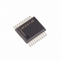
MAX4533CAP+ Maxim Integrated Products, MAX4533CAP+ Datasheet

MAX4533CAP+
Specifications of MAX4533CAP+
Related parts for MAX4533CAP+
MAX4533CAP+ Summary of contents
Page 1
... V4 FLYING CAPACITOR LEVEL TRANSLATOR (2-CHANNEL) Rail-to-Rail is a registered trademark of Nippon Motorola, Ltd. † Pg ________________________________________________________________ Maxim Integrated Products For pricing, delivery, and ordering information, please contact Maxim/Dallas Direct! at 1-888-629-4642, or visit Maxim’s website at www.maxim-ic.com. SPDT Analog Switch o Rail-to-Rail Signal Handling o ±40V Fault Protection with Power Off ± ...
Page 2
Quad, Rail-to-Rail, Fault-Protected, SPDT Analog Switch ABSOLUTE MAXIMUM RATINGS Voltages Referenced to GND V+ ........................................................................-0.3V to +44.0V V- .........................................................................-44.0V to +0. V-................................................................-0.3V to +44.0V COM_, IN_ (Note 1) ............................. (V- - 0.3V) to (V+ + 0.3V) NC_, NO_ ...
Page 3
Quad, Rail-to-Rail, Fault-Protected, ELECTRICAL CHARACTERISTICS—Dual Supplies (continued) (V+ = +15V -15V MIN MAX PARAMETER SYMBOL NO_ or NC_ Input Leakage I NO_, Current, Supplies Off COM_ On-Clamp Output I Current, Supplies On ...
Page 4
Quad, Rail-to-Rail, Fault-Protected, SPDT Analog Switch ELECTRICAL CHARACTERISTICS—Single Supply (V+ = +12V unless otherwise noted. Typical values are MIN MAX PARAMETER SYMBOL ANALOG SWITCH Fault-Free Analog Signal Range ...
Page 5
Quad, Rail-to-Rail, Fault-Protected, ELECTRICAL CHARACTERISTICS—Single Supply (continued) (V+ = +12V unless otherwise noted. Typical values are MIN MAX PARAMETER SYMBOL SWITCH DYNAMIC CHARACTERISTICS Turn-On Time Turn-Off Time Break-Before-Make ...
Page 6
Quad, Rail-to-Rail, Fault-Protected, SPDT Analog Switch (V+ = +15V -15V +25°C, unless otherwise noted.) A ON-RESISTANCE vs. V COM (DUAL SUPPLIES) 390 V± = ±4.5V 360 330 300 270 240 210 V± = ±10V V± = ...
Page 7
Quad, Rail-to-Rail, Fault-Protected, (V+ = +15V -15V +25°C, unless otherwise noted.) A TURN-ON/TURN-OFF TIME vs. TEMPERATURE (SINGLE SUPPLY) 250 200 t ON 150 t OFF 100 +12V -55 -35 ...
Page 8
Quad, Rail-to-Rail, Fault-Protected, SPDT Analog Switch (V+ = +15V -15V +25°C, unless otherwise noted.) A FREQUENCY RESPONSE (DUAL SUPPLIES) 0 -10 BANDWIDTH -20 -30 -40 -50 OFF ISOLATION -60 CROSSTALK -70 -80 -90 -100 0.01 0.1 ...
Page 9
Quad, Rail-to-Rail, Fault-Protected, -15V COMPARATOR N-CHANNEL DRIVER -15V N3 SENSE SWITCH NC_ N1 or INPUT NO_ P1 P3 SENSE SWITCH P-CHANNEL +15V DRIVER COMPARATOR +15V Figure 1. Simplified Internal Structure During normal operation of a conducting channel, N1 and P1 ...
Page 10
Quad, Rail-to-Rail, Fault-Protected, SPDT Analog Switch Table 1. Switch States in Normal and Fault Conditions POWER INPUT SUPPLIES RANGE (V+, V-) On Between Rails On Between Rails On Between V+ and (+40V - V+) On Between V+ and (+40V - ...
Page 11
Quad, Rail-to-Rail, Fault-Protected, LOGIC +3V INPUT 50 COM SWITCH OUTPUT V COM SWITCH t D OUTPUT Figure 3. Break-Before-Make IN_ IN_ 50Ω MAX4533 NC_ OR NO_ GND ...
Page 12
... Maxim reserves the right to change the circuitry and specifications without notice at any time. implied. Maxim reserves the right to change the circuitry and specifications without notice at any time. 12 ____________________Maxim Integrated Products, 120 San Gabriel Drive, Sunnyvale, CA 94086 408-737-7600 12 ____________________Maxim Integrated Products, 120 San Gabriel Drive, Sunnyvale, CA 94086 408-737-7600 © ...


